
TM 5-3895-379-23-1
0081
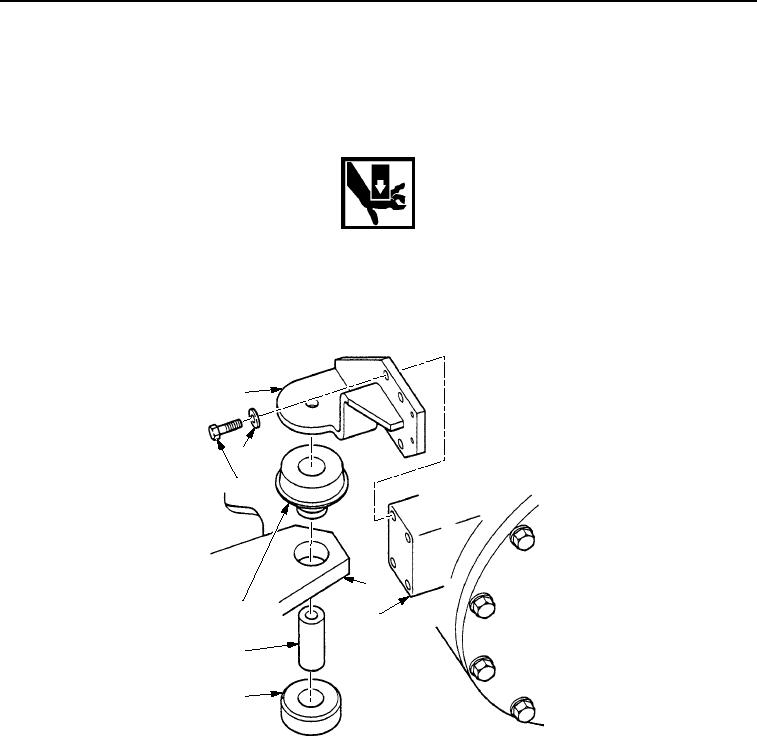
REMOVAL - Continued
6.
With assistance, use lifting device to raise engine (Figure 5, Item 3) until there is a space between resilient
mounts (Figure 5, Item 4) and rear engine mounts (Figure 5, Item 1) or frame assembly (Figure 5, Item 2).
WARNING
Do not place fingers between engine mount and frame assembly. Shifting engine may cause
injury.
7.
Remove eight bolts (Figure 5, Item 6), washers (Figure 5, Item 7), two rear engine mounts (Figure 5, Item 1),
two resilient mounts (Figure 5, Item 4), and remaining spacer sleeves (Figure 5, Item 5) from engine
(Figure 5, Item 3) and frame assembly (Figure 5, Item 2).
1
7
6
2
4
3
5
4
M0063SWR
Figure 5.
Rear Engine Mount Removal.
END OF TASK
03/15/2011Rel(1.8)root(maintwp)wpno(M00020)