
TM 5-3895-379-23-1
0081
INSTALLATION
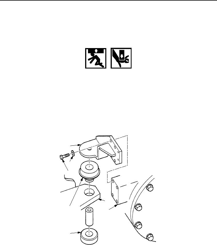
1.
Install two rear engine mounts (Figure 6, Item 1) on engine (Figure 6, Item 3) with eight washers
(Figure 6, Item 6) and bolts (Figure 6, Item 5). Tighten bolts to 60-90 lb-ft (80-120 Nm).
WARNING
Use caution when handling heavy parts. Provide adequate support and use assistance during
procedure. Ensure that any lifting device used is in good condition and of suitable load
capacity. Keep clear of heavy parts supported only by lifting device. Failure to follow this
warning may cause injury or death.
NOTE
Engine weighs 2,000 lb (907 kg).
2.
Position two resilient mounts (Figure 6, Item 4) between two rear engine mounts (Figure 6, Item 1) and frame
assembly (Figure 6, Item 2).
3.
With assistance, use lifting device to lower engine (Figure 6, Item 3).
1
6
5
2
4
3
4
M1129SWR
Figure 6. Rear Engine Mount Installation.
4.
Install two spacer sleeves (Figure 7, Item 6), washers (Figure 7, Item 7), bolts (Figure 7, Item 1), washers
(Figure 7, Item 4), and nuts (Figure 7, Item 5) in two rear engine mounts (Figure 7, Item 2) and frame assembly
(Figure 7, Item 3).
5.
Tighten nuts (Figure 7, Item 5) to 145-205 lb-ft (197-278 Nm).
03/15/2011Rel(1.8)root(maintwp)wpno(M00020)