
SECTION 9
STEERING
g. Fold boots over the ball joints and secure their
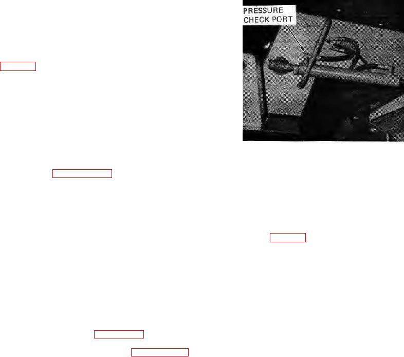
9-86. CHECKING RELIEF PRESSURE (see figure 9-
position with the metal ribbons.
95).
9-83.
BLEEDING THE SYSTEM.
9-87.
Pressure can be checked at the base of the
steering cylinder fitting. Use a gauge rated at
2
9-84. Air may become trapped in the system if any
3000 PSI (200 kg/cm ) or greater.
Oil
hoses or components are removed. An aerated system Is
temperature should be approximately 100 F.
indicated by jerky or spongy operation when the steering
(37 C).
To check pump output pressure,
wheel is turned.
proceed as follows:
9-85. All hydraulic hoses leading to and from the
cylinder enter at the top of the cylinder. Therefore, the
system can be bled without disconnecting the hoses.
Bleed the system as follows:
a. Fill the hydraulic tank with the specified oil (refer
to Section 4).
b. Start the engine and allow to idle at 500 to 600
RPM for approximately one minute. This allows large. air
bubbles in the system to escape.
WARNING: Do not extend the hands or arm through the
center of the steering wheel. If the steering
control unit has been disassembled and
incorrectly timed, the wheel may suddenly
FIGURE 9-95.
become motorized or rotate abruptly with
extreme force. If this occurs, see figure 9-2
a. Remove the plug at the steering cylinder base
and paragraph 9-27, step t and retime the
inlet fitting.
control unit as shown.
b. Connect pressure gauge to the cylinder fitting.
c. Increase engine speed to approximately 1, 000
RPM and rotate the steering wheel as fast as possible in
c. Start the engine and set speed at high idle.
either direction.
This should produce enough
Rotate steering wheel from stop-to-stop. As guide rolls
compression of oil to force the air out of the lines.
reach stops, the pressure gauge should indicate relief
pressure (refer to Section 2).
d. Continue to rotate the wheel in the same direction
until the guide roll reaches its limit. Quickly reverse the
CAUTION: Do not hold system over relief for longer than
steering wheel rotation to pressurize the opposite end of
20 seconds. This will damage the pump.
the steering cylinder.
NOTE: If proper pressure is not obtained, remove the
e. Continue to rotate the wheel left and right, from
relief valve and clean all parts thoroughly. Carefully
stop to stop, until steering control is normal.
check the relief valve spool for burrs. Install the valve
and recheck the pressure. If proper pressure cannot be
NOTE: If steering control fails to return to normal, air
may be entering the system at the suction side
of the pump (see figure 9-82). Check and
tighten all hose fittings securely. Also check
system pressure as specified in paragraph 9-86.
9-30.