
SECTION 9
STEERING
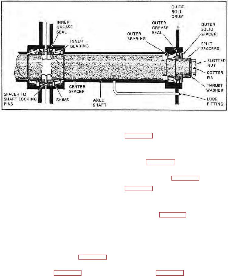
FIGURE 9-101.
c. Insert center spacer on shaft and install locking pins
b. Inspect all seals. Replace any seals that are cut,
(see figure 9-104).
worn or otherwise have a doubtful remaining service life.
d. Install shim(s) in original location (see step e,
c. Inspect all bearings for cracks, nicks, galling,
paragraph 9-101). Insert shaft assembly Into one drum,
brinelling, etc. Replace all parts that are defective or have
then insert the other drum into the other side of the shaft
a doubtful remaining service life.
assembly (see figure 9-105).
d. Check bearing surfaces for evidence of bearings
e. Install outer bearing, grease seal, and outer solid
turning on the shaft. If bearing Inner race is turning, check
spacer into each drum (see figure 9-106).
concentricity of the shaft. Repair or replace if found to be
f. Install split spacers, thrust washers, and slotted nuts
eccentric or badly worn. Slight imperfections of the shaft
(see figure 9-107).
may be removed with fine sandpaper. Check the roller
bearing surfaces of the shaft for nicks, galling and cracks.
g. Working at each end separately, torque slotted nut
Repair or replace shaft if any of these are found or if a
to 200 ft.-lbs. (27.7 kg-m); back off to 25 ft.-lbs. (3.5 kg-m),
definite step can be felt between the worn and unworn
then retorque to 45 ft.-lbs. (6.3 kg-m) or next higher slot.
surfaces when checked with fingernail.
Install cotter pin (see figure 9-108).
e. Clean the shaft cavity of the drums with solvent and
dry thoroughly.
NOTE:
Ensure that the drums are on a flat, level
surface. Placing one drum on a pallet and the other drum
9-95. REASSEMBLY OF AXLE SHAFT ASSEMBLY.
supported with a lift truck or hand dolly will allow the drums
to easily assemble together.
a. Lubricate all bearing cup bores (four), then install
h. Check to see If clearance between guide rolls is
bearing cups (one inner and outer cup per drum) into the
within specifications. If correct clearance does not exist,
drums. Be sure cups are firmly seated (see figure 9-102).
remove one drum and adjust shim pack between center
spacer and bearing to maintain .010 - .030 in. (.25 - .76
b. Install inside bearing cones and grease seals into
mm) clearance (see figure 9-109).
inside hubs on both drums (see figure 9-103).
9-33.