
SECTION 7
TRANSMISSION
FIGURE 7-16.
FIGURE 7-22.
FIGURE 7-21.
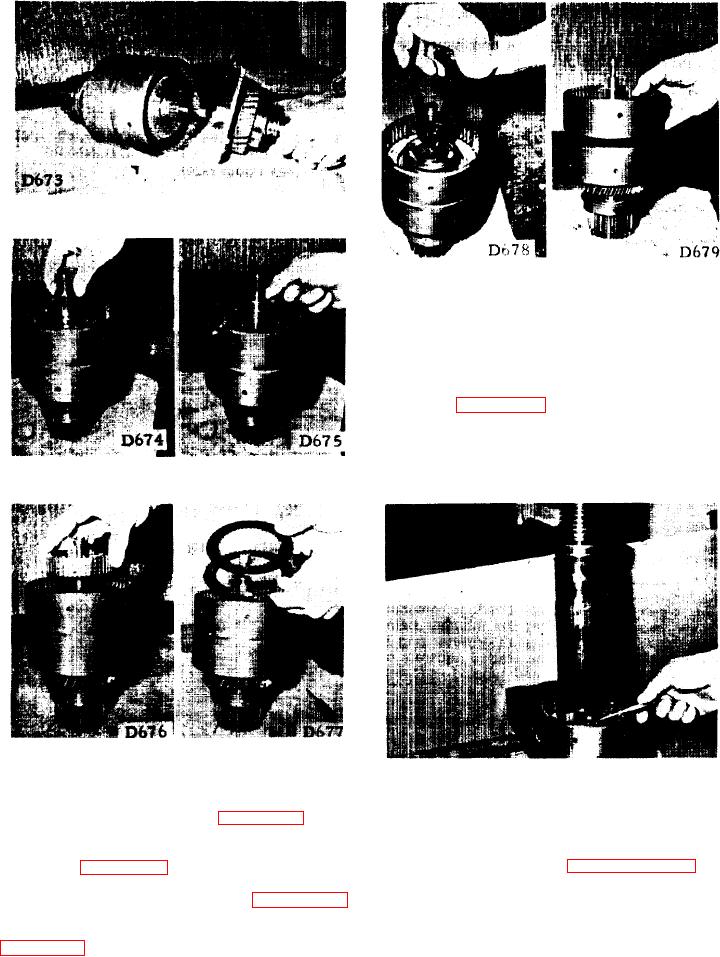
FORWARD CLUTCH CYLINDER
7-27.
DISASSEMBLY.
a . Put the clutch cylinder under an arbor
press and compress the springs with a set of
b a r s . Remove the lock ring and unload the
spring (see figure 7-23).
b. Apply an air pressure nozzle to the oil
holes in the bore of the clutch cylinder to force
the clutch piston out.
FIGURE 7-17.
FlGURE 7-18.
FIGURE 7-20.
FIGURE 7-19.
FIGURE 7-23.
c. Insert the nose of a pair of needle nose
p l i e r s into one of the holes in the forward
REVERSE CLUTCH CYLINDER
7-28.
clutch hub and lift it out (see figure 7-19).
DISASSEMBLY.
d . Remove the separator and the friction
a. Repeat procedures in paragraphs 7-26 and
plates (see figure 7-20).
7-27 to disassemble the reverse clutch pack.
e. Remove the snap ring (see figure 7-21)
b. If necessary, remove the bearings from
f r o m the output shaft which frees the front
the input and output shafts and the cast iron
c l u t c h cylinder. Remove this cylinder (see
oil seals from the output shafts.
7-7