TM 5-3895-383-24
Pistons And Rings
One Piece Pistons
NOTE:
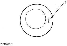
Engines which use one piece pistons (1) have the
word "FRONT" stamped on the crown of the
piston. Make sure the word "FRONT" is toward
the front of the engine when the piston is
installed. The front of the engine is opposite the
flywheel end. Install the piston and connecting
rod groups with the rod forging part number
facing to the rear of the engine. The rear of the
engine is the flywheel end. The two piece pistons
are not stamped with the word "FRONT" because
orientation is not necessary.
Top And Intermediate Ring
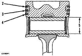
Install piston ring with "UP" side toward top of piston.
(2)
Top Ring has the mark "UP-1".
Clearance between ends of piston ring when installed in
a cylinder:
3114 & 3116 with a bore size of 105.025 mm
(4.1348 in) ...................0.525 ± 0.125 mm (.021 ± .005 in)
3126 with a bore size of 110.025 mm
(4.3317 in) ...................0.56 0.10 mm (.0221 ± .0040 in)
3114 & 3116 increase in clearance between ends of
piston ring for each 0.03 mm (.001 in) increase in
cylinder bore size ....................................0.09 mm (.004 in)
3126 increase in clearance between ends of piston ring
for each 0.01 mm (.00040 in) increase in cylinder bore
size ........................................................0.031 mm (.0012 in)
After rings have been installed, rotate so end gaps are
apart ...................................................................120 degrees
(3)
Intermediate Ring has the mark "UP-2".
Clearance between ends of piston ring when installed in
a cylinder:
3114 & 3116 with a bore size of 105.025 mm
(4.1348 in) ...................0.828 ± 0.125 mm (.033 ± .005 in)
3126 with a bore size of 110.025 ± 0.025 mm
(4.3317 ± .0001 in).................................0.904 ± 0.125 mm
(.0356 ± .0050 in)
3114 & 3116 increase in clearance between ends of
piston ring for each 0.03 mm (.001 in) increase in
cylinder bore size ....................................0.09 mm (.004 in)
3126 increase in clearance between ends of piston ring
for each 0.01 mm (.00040 in) increase in cylinder bore
size ........................................................0.031 mm (.0012 in)
After rings have been installed, rotate so end gaps are
apart ...................................................................120 degrees
Oil Control Ring
(4)
Install Oil Control Ring with the gap in the spring 180
degrees away from the gap in the ring. Painted portion
of spring must be visible at the ring end gap.
Width of groove in piston for piston ring
(new) ........................4.041 ± 0.013 mm (.1591 ± .0005 in)
Thickness of piston ring (new) .............3.982 ± 0.008 mm
(.1568 ± .0003 in)
Clearance between groove and piston ring
(new) ..................... 0.038 to 0.080 mm (.0015 to .0031 in)
Clearance between ends of piston ring when installed in
a cylinder:
3114 & 3116 with a bore size of 105.025 mm
(4.1348 in) ........................0.45 ± 0.15 mm (.018 ± .006 in)
3126 with a bore size of 110.025 ± 0.025 mm
(4.3317 ± .0001 in).................................. 0379 ± 0.100 mm
(.0149 ± .0040 in)
3114 & 3116 increase in clearance between ends of
piston ring for each 0.03 mm (.001 in) increase in
cylinder bore size ....................................0.09 mm (.004 in)
5-29


