TM 5-3895-383-24
Crankshaft
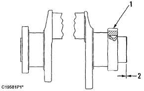
(1)
Heat gear to install. Do not heat
above...............................................................316C (600F)
(2)
End play for crankshaft assembled in
engine ............................ 0.07 to 0.32 mm (.003 to .013 in)
Crankshaft Pulley Group
(1)
Bolt. Tighten bolts to a torque of.................200 ± 25 N m
(150 ± 18 lb-ft)
Connecting Rods
(1)
Bore in bearing for piston pin
(new) ................... 40.028 ± 0.008 mm (1.5759 ± .0003 in)
To install bearing, rod may be heated at length (A) (do
not use a torch) to ...........................................175 to 260C
(347 to 500F)
Length (A) ........................................... 75 ± 5 mm (3 ± .2 in)
Bearing joint must be at either location (B) at an angle
above bore centerline of..............................12 ± 5 degrees
Diameter of piston pin (new) ..............40.000 ± 0.005 mm
(1.5748 ± .0002 in)
(2)
Distance between center of bearings ............. 200.00 mm
(7.874 in)
(3)
Location for etching cylinder number on rod and cap
after assembly. Etch numbers on same side of rod as
bearing retainer notch.
(4)
Tighten connecting rod bolts as follows:
a.
Before assembly, put 4C5593 Thread Lubricant or
clean engine oil on the bolt threads and all surfaces
that make contact between the bolt and cap.
b.
Tighten each nut to ..................54 ± 7 N m (40 ± 5 lb-ft)
c.
Put an alignment mark on cap and nut.
d.
Tighten each nut an
additional ................................. 60 ± 5 degrees (1/6 turn)
(5)
Bore in connecting rod for bearing with bolts tightened
to specification (4) ................................75.000 ± 0.013 mm
(2.9528 .0005 in)
5-28


