TM 5-3895-382-24
NOTE: Steps 14 through 22 are for the disassembly of
the differential.
14.
Put an alignment mark on the case and cover assembly
of the differential for assembly purposes. The
components must be reinstalled in their original
positions.
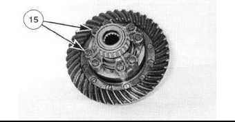
15.
Loosen, but do not remove eight bolts (15) that hold the
case to the cover.
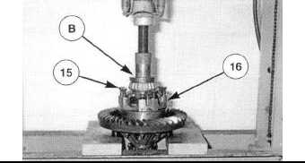
16.
Put the differential in a press as shown. Install Tooling
(B) on the end of the differential as shown. Apply
pressure on the differential so it can not move in the
press. Remove eight bolts (15) and the washers that
hold the case and cover together. Slowly release the
pressure on the differential until all the spring force
under cover (16) is released.
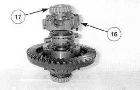
17.
Remove cover (16) from the No-Spin differential.
Remove bearing cone (17) from the cover.
NOTE: The No-Spin differential is serviced as a unit.
However, it can be disassembled for cleaning
purposes.
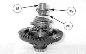
18.
Remove side gear (18), spring retainer (19) and spring
(20).
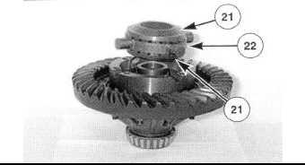
19.
Remove two drive clutch assemblies (21) and spider
assembly (22). Separate the drive clutch assemblies
and the spider assembly.
16-101

