TM 5-3895-382-24
b.
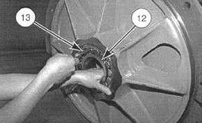
To check the clearance between the bearing roller
and the outer race, stand the bearing housing up
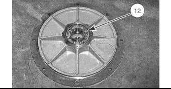
vertically. Hold bearing (12) in position with one hand
and using feeler gauge (13) with the other, side the
feeler gauge between the bearing roller and the outer
race at the "12 o'clock" position. Do not rotate the
bearing rollers over the top of the feeler gauge as this
will give a false reading. The clearance between the
bearing rollers and the outer race should be .102 to
.152 mm (.004 to .006 in).
14.
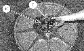
If it is necessary to remove bearings (12) from bearing
housings (2) and (8), insert Tool (C) through bearing
(12) as shown.
15.
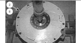
Position the bearing housing in a press as shown. Use
the press and Tool (C) to remove bearing (12) from the
bearing housings.
Assemble Drum Assembly 6605-016
Tools Needed
A
B
C
6V-2157
Line Bracket
2
FT-2434
Shaft Support Assembly
1
8T-5096
Dial Indicator Test Group
1
NOTE:
Clean the drum reservoir, all internal parts and
bearing housings thoroughly before assembly of
the drum assembly.
1.
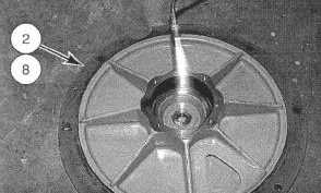
If is necessary to install new bearings into bearing
housings (2) and (8), heat the bearing housings to a
maximum temperature of 82° C (180° F) as shown.
2.
Install bearing (12) in each of the bearing housings.
The bearings should drop into position.
NOTE:
Install the bearings with the bearing nomenclature
facing up.
16-44

