
TM 5-3895-379-23
TROUBLESHOOTING PROCEDURES - CONTINUED
0006 00
Table 6. Vibratory System Troubleshooting Procedures - Continued.
MALFUNCTION
TEST OR INSPECTION
CORRECTIVE ACTION
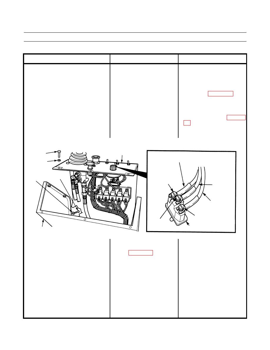
Vibration Only Occurs While Vibration 4. Check for power at amplitude 1. If 24 to 28 Vdc are not measured
7.
select switch. Set amplitude
at terminals 1 and 3, turn engine
Control Switch Is Set To Manual Mode
select switch to high pitch (push
start switch and battery disconnect
- Continued.
forward). Touch positive (+)
switch to OFF position (TM 5-
probe of multimeter to terminal 1
3895-379-10). Replace amplitude
(wire B921-WH) and negative (-
select switch (WP 0073 00).
) probe of multimeter to good
ground. Measure Vdc. Set 2. If 24 to 28 Vdc are measured at
terminals 1 and 3, repair or replace
amplitude select switch to low
wiring and connectors from
pitch (pull back). Touch positive
amplitude select switch (WP 0108
(+) probe of multimeter to
terminal 3 (wire C920-GN) and
negative (-) probe of multimeter
to good ground.
PANEL
ASSEMBLY
SCREW
WIRE C920-GN
WASHER
SCREW
TERMINAL 3
WASHER
WIRE
C933-GN
WIRE
B921-WH
TERMINAL 1
TERMINAL 2
AMPLITUDE SELECT SWITCH
OPERATOR STATION
401-229
1. Adjust propel control lever If vibration still does not occur, go to
8.
Vibration Only Occurs While
vibratory system engagement Step 2.
Vibration Control Switch Is Set To
stops (WP 0114 00).
Automatic Mode.
