
TM 5-3895-379-23
TROUBLESHOOTING PROCEDURES - CONTINUED
0006 00
Table 2. Electrical Troubleshooting Procedures - Continued.
MALFUNCTION
TEST OR INSPECTION
CORRECTIVE ACTION
6.
Starting Aid Switch Does Not Work.
WARNING
Remove all jewelry such as rings, dog tags and bracelets. If jewelry
contacts electrical connection, a direct short may occur resulting in
injury or death and damage to equipment.
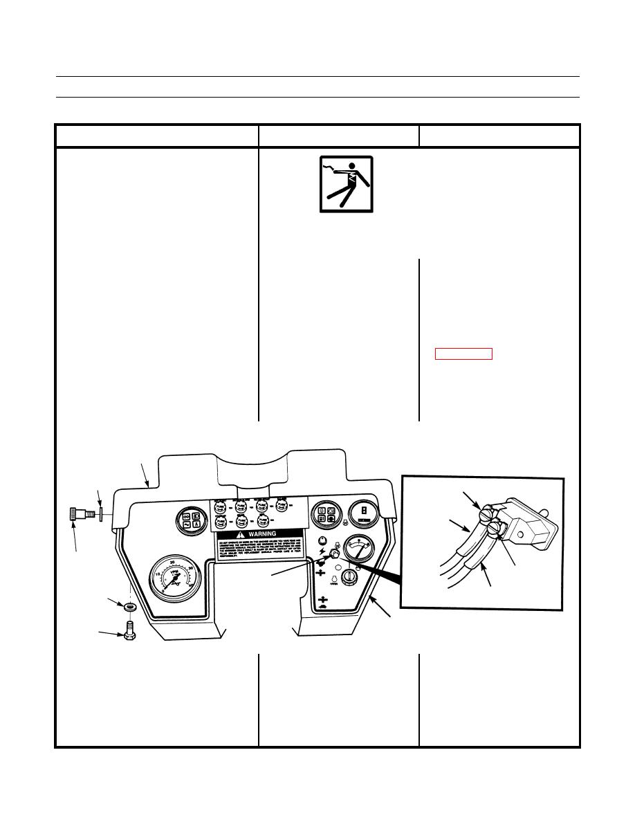
1. Check for power to starting aid 1. If 24 to 28 Vdc are not measured
switch. Remove two shoulder
at terminal 2 and START AID fuse
screws, washers and vandal guard
is good, turn engine start switch
from box assembly. Remove
and battery disconnect switch to
three screws and washers and lift
OFF position (TM 5-3895-379-
box assembly up from operator
10). Repair or replace wiring and
station. Turn battery disconnect
connectors to starting aid switch
switch and engine start switch to
ON position (TM 5-3895-379-
10). Touch positive (+) probe of 2. If 24 to 28 Vdc are measured at
terminal 2, go to Step 2.
multimeter to terminal 2 (wire
148-WH) and negative (-) probe
of multimeter to good ground.
VANDAL
GUARD
WASHER
TERMINAL 1
WIRE 376-GN
SHOULDER
SCREW
TERMINAL 2
STARTING
WASHER
AID SWITCH
WIRE 148-WH
BOX ASSEMBLY
SCREW
401-203
