
TM 5-3895-379-23-2
0269
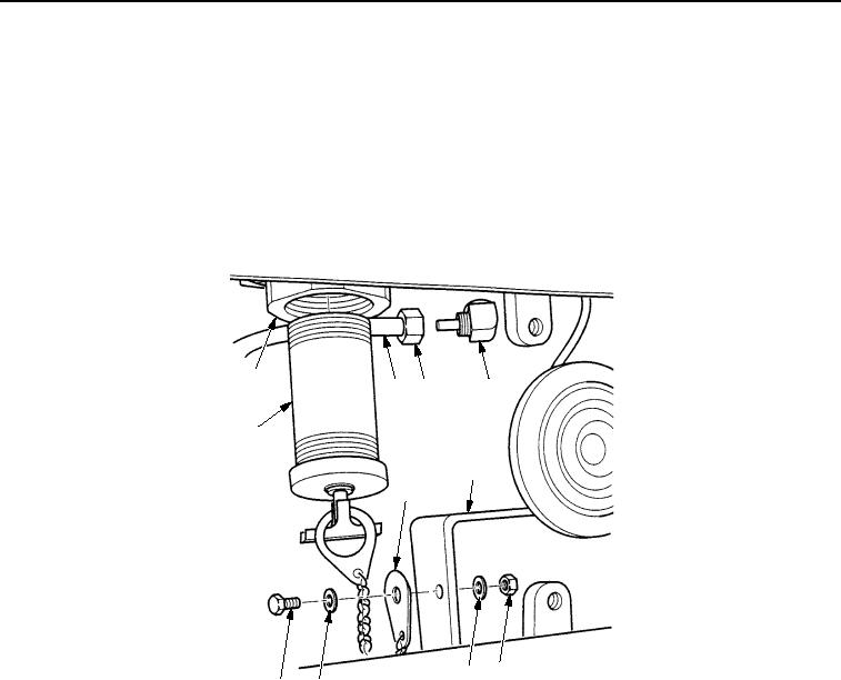
INSTALLATION - Continued
6.
Apply sealing compound to threads of nipple (Figure 9, Item 9) and install nipple in water tank
(Figure 9, Item 10).
7.
Install cap assembly (Figure 9, Item 7) on bumper bracket (Figure 9, Item 4) with bolt (Figure 9, Item 8), two
washers (Figure 9, Item 6), and new locknut (Figure 9, Item 5). Tighten locknut to 84-132 lb-in. (9-15 Nm).
8.
Install cap assembly (Figure 9, Item 7) on nipple (Figure 9, Item 9) by turning tee-handle fully right until cap
assembly is snug in nipple.
9.
Position tube (Figure 9, Item 1) on elbow (Figure 9, Item 3) and tighten fitting (Figure 9, Item 2).
10
1
2
3
9
4
7
5
6
6
8
M0246SWR
Figure 9. Water Tank Installation.
03/15/2011Rel(1.8)root(maintwp)wpno(M00207)