
TM 5-3895-379-23-2
0260
REMOVAL - Continued
NOTE
Use drain pan to catch any hydraulic oil that may drain from system. Dispose of oil IAW local
policy and ordinances. Ensure all spills are cleaned up.
14.
Turn hydraulic oil cooler over and drain fluid into 5 gal (19 Liters) drain pan.
15.
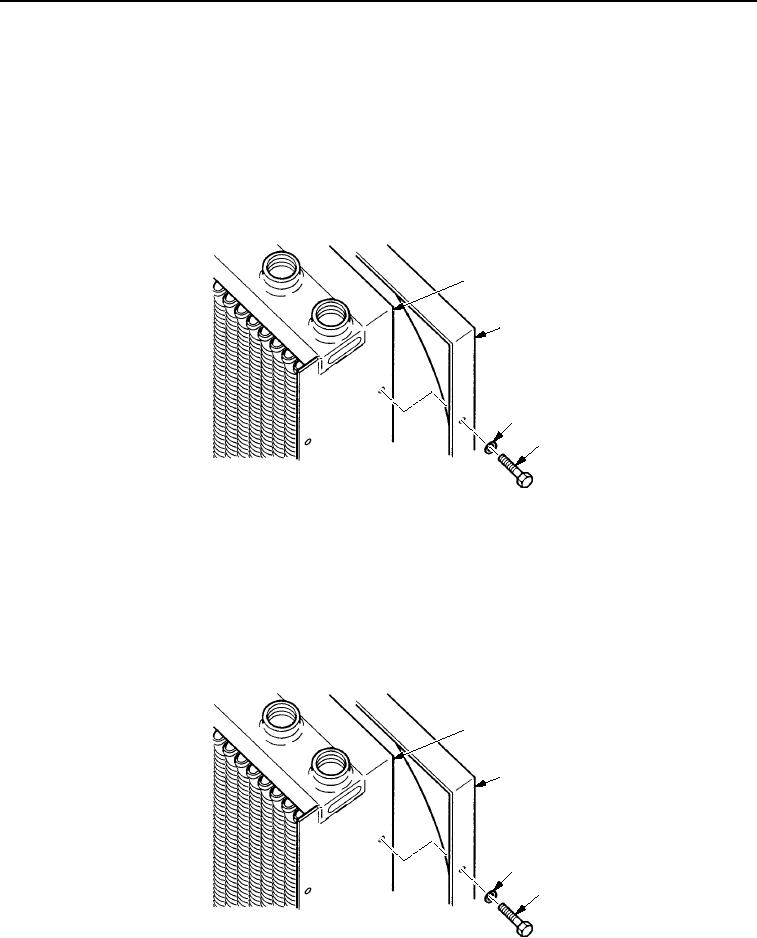
Remove eight screws (Figure 6, Item 4), washers (Figure 6, Item 3), and fan shroud (Figure 6, Item 2) from
hydraulic oil cooler (Figure 6, Item 1).
1
2
3
4
M0180SWR
Figure 6. Hydraulic Oil Cooler and Fan Shroud Removal.
END OF TASK
INSTALLATION
1.
Install fan shroud (Figure 7, Item 2) on hydraulic oil cooler (Figure 7, Item 1) with eight washers
(Figure 7, Item 3) and screws (Figure 7, Item 4).
1
2
3
4
M1267SWR
Figure 7.
Hydraulic Oil Cooler and Fan Shroud Installation.
03/15/2011Rel(1.8)root(maintwp)wpno(M00198)