
TM 5-3895-379-23-1
0197
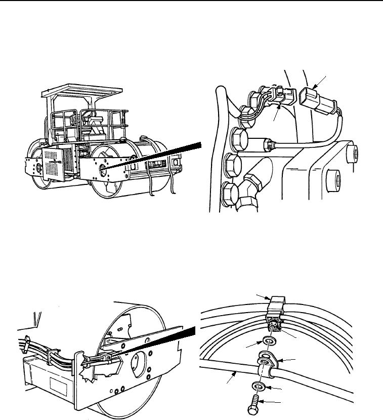
INSTALLATION - Continued
10.
Connect front vibratory sensor connector (Figure 18, Item 1) to front wiring harness connector
(Figure 18, Item 2).
1
2
M0301SWR
Figure 18. Front Wiring Harness Installation.
11.
Install clip (Figure 19, Item 1) on front wiring harness (Figure 19, Item 6).
12.
Install washer (Figure 19, Item 4), clip (Figure 19, Item 3), washer (Figure 19, Item 4), and screw
(Figure 19, Item 5) to welded nut (Figure 19, Item 2) on clip assembly (Figure 19, Item 1).
1
2
4
3
6
4
5
M0302SWR
Figure 19. Front Wiring Harness Installation.
13.
Install bracket (Figure 20, Item 1) to frame assembly (Figure 20, Item 4) with washer (Figure 20, Item 2) and
screw (Figure 20, Item 3).
03/15/2011Rel(1.8)root(maintwp)wpno(M00135)