
TM 5-3895-379-23-1
0196
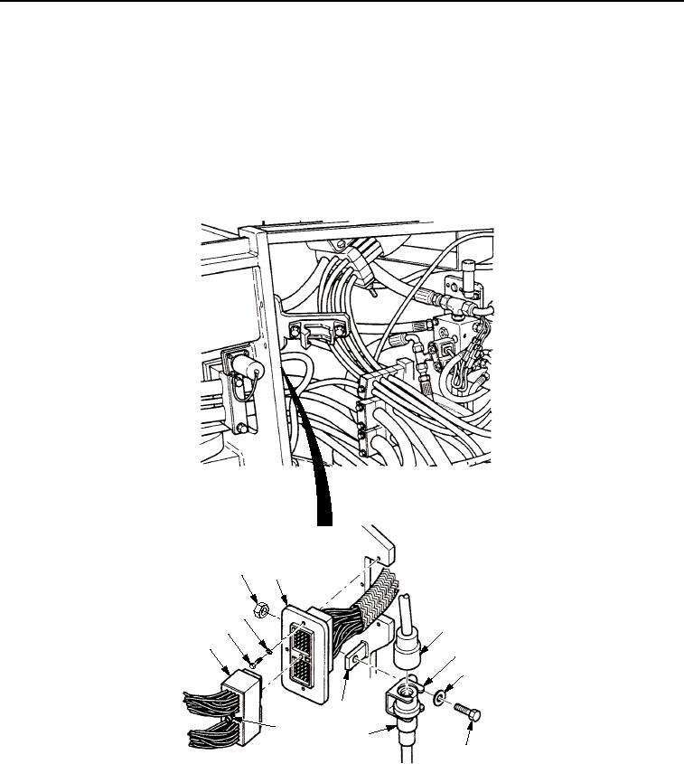
INSTALLATION - Continued
24.
Install engine wiring harness connector (Figure 34, Item 2) to frame assembly (Figure 34, Item 8) with three
new lockwashers (Figure 34, Item 12) and screws (Figure 34, Item 11).
25.
Connect engine wiring harness connector (Figure 34, Item 2) to connector (Figure 34, Item 10) and tighten
screw (Figure 34, Item 9).
26.
If removed, install bracket (Figure 34, Item 4) to frame assembly (Figure 34, Item 8) with screw
(Figure 34, Item 6), washer (Figure 34, Item 5), and nut (Figure 34, Item 1).
27.
Connect engine wiring harness connector (Figure 34, Item 3) to connector (Figure 34, Item 7).
1
2
12
11
3
10
4
5
8
9
7
6
M1044SWR
Figure 34. Engine Wiring Harness Installation.
END OF TASK
03/15/2011Rel(1.8)root(maintwp)wpno(M00134)