
TM 5-3895-379-23-1
0196
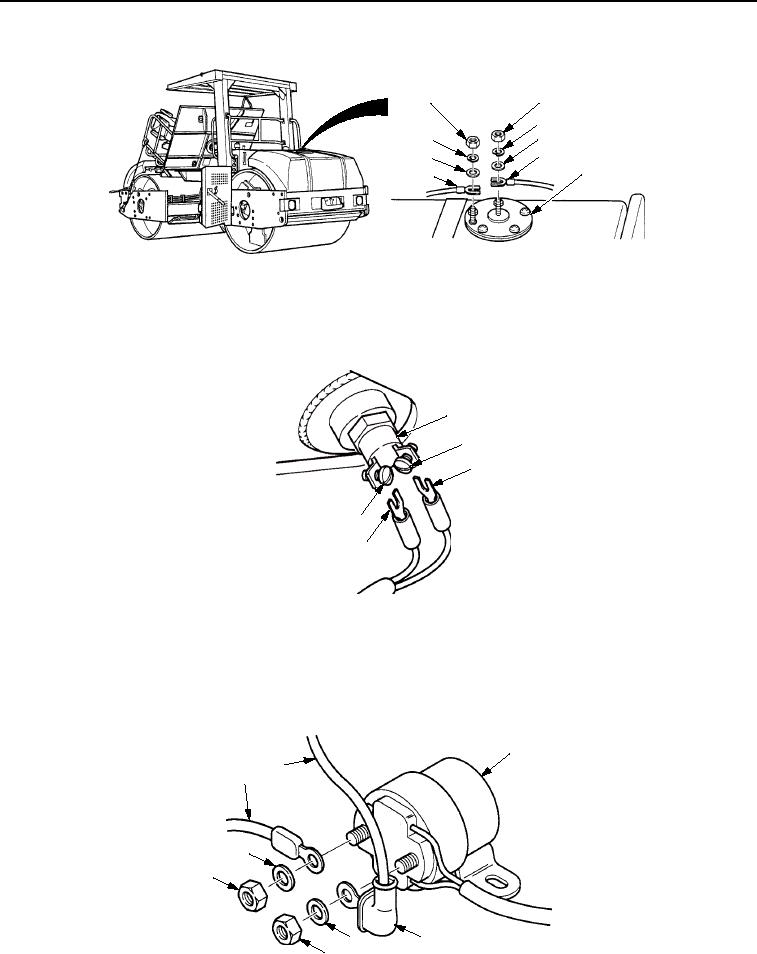
INSTALLATION - Continued
1
1
2
3
2
4
3
5
4
M1030SWR
Figure 20. Engine Wiring Harness Installation.
6.
Position two wires (Figure 21, Item 3) on hydraulic temperature sensor (Figure 21, Item 1) and tighten two
screws (Figure 21, Item 2).
1
2
3
2
3
M1031SWR
Figure 21. Engine Wiring Harness Installation.
7.
Install two cables (Figure 22, Items 1 and 2) on starter relay switch assembly (Figure 22, Item 3) with two
washers (Figure 22, Item 5) and nuts (Figure 22, Item 6). Position boot (Figure 22, Item 4) to cover cable
(Figure 22, Item 2).
3
2
1
5
6
5
4
6
M1032SWR
Figure 22. Engine Wiring Harness Installation.
03/15/2011Rel(1.8)root(maintwp)wpno(M00134)