
TM 5-3895-379-23-1
0196
REMOVAL - Continued
20.
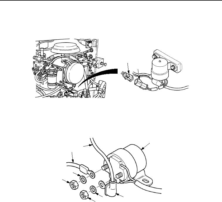
Disconnect engine wiring harness connector (Figure 12, Item 1) from starter relay connector
(Figure 12, Item 2).
1
2
M1022SWR
Figure 12. Engine Wiring Harness Removal.
21.
Position boot (Figure 13, Item 4) so that end of cable (Figure 13, Item 2) can be seen and remove two nuts
(Figure 13, Item 6), washers (Figure 13, Item 5), and two cables (Figure 13, Items 1 and 2) from starter relay
switch assembly (Figure 13, Item 3).
3
2
1
5
6
4
5
6
M1023SWR
Figure 13. Engine Wiring Harness Removal.
03/15/2011Rel(1.8)root(maintwp)wpno(M00134)