
TM 5-3895-379-23-1
0159
INSTALLATION
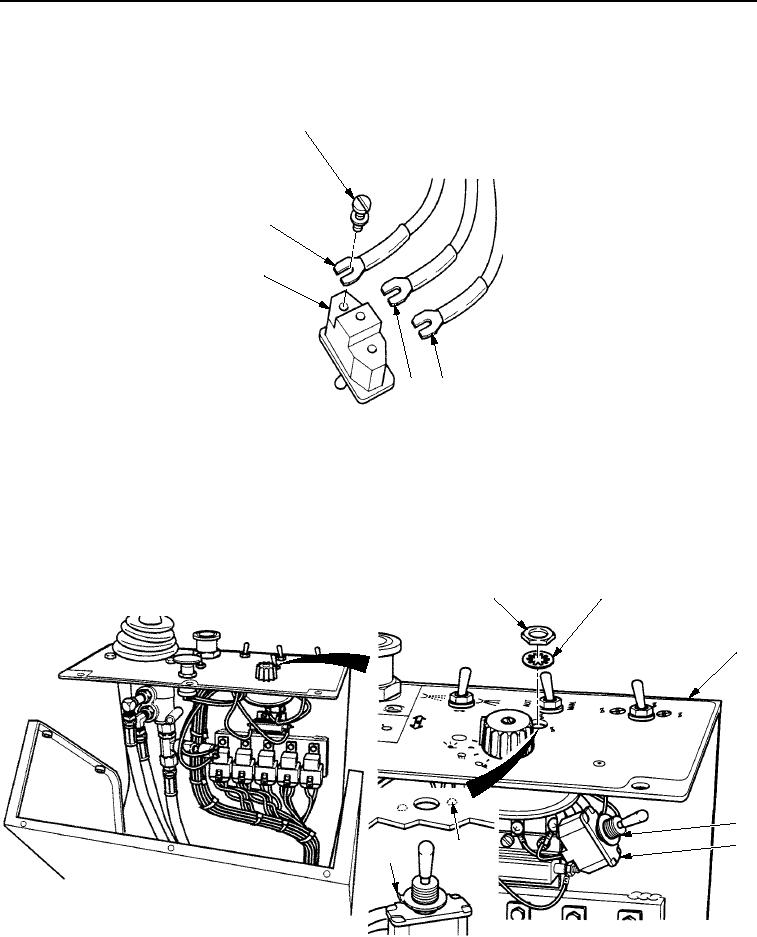
1.
Install three wires (Figure 4, Items 2, 3, and 5) on vibration control switch (Figure 4, Item 4) with three screws
(Figure 4, Item 1).
1
5
4
2
3
M1221SWR
Figure 4. Vibration Control Switch Installation.
NOTE
Tab of ring (Figure 5, Item 7) fits in notch (Figure 5, Item 6) of panel assembly to properly
align vibration control switch in panel assembly.
2.
Install vibration control switch (Figure 5, Item 5) on panel assembly (Figure 5, Item 3) with ring
(Figure 5, Item 4), new lockwasher (Figure 5, Item 2), and nut (Figure 5, Item 1).
1
2
3
4
5
6
7
VIEW FROM DRIVER'S SEAT
M1304SWR
Figure 5. Vibration Control Switch Installation.
03/15/2011Rel(1.8)root(maintwp)wpno(M00097)