
TM 5-3895-379-23-1
0159
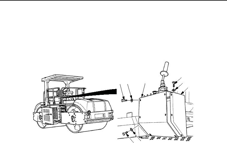
REMOVAL
1.
Remove two screws (Figure 1, Item 1) and washers (Figure 1, Item 5) from operator station (Figure 1, Item 4).
2.
Remove seven screws (Figure 1, Item 1) and washers (Figure 1, Item 2) from operator station
(Figure 1, Item 4).
3.
Lift panel assembly (Figure 1, Item 3) and pull away from operator station (Figure 1, Item 4).
1
3
1
2
2
4
5
1
M0869SWR
Figure 1.
Vibration Control Switch Removal.
4.
Remove nut (Figure 2, Item 1), lockwasher (Figure 2, Item 2), vibration control switch (Figure 2, Item 5), and
ring (Figure 2, Item 4) from panel assembly (Figure 2, Item 3). Discard lockwasher.
03/15/2011Rel(1.8)root(maintwp)wpno(M00097)