
TM 5-3895-379-23-1
FIELD MAINTENANCE
DRUM SELECT SWITCH REPLACEMENT
INITIAL SETUP:
References
Tools and Special Tools
TM 5-3895-379-23P, Figure 49
Tool Kit, General Mechanic's: Automotive
(Volume 2, WP 0289, Table 1, Item 39)
Equipment Condition
Engine off. (TM 5-3895-379-10)
Materials/Parts
Drums chocked. (TM 5-3895-379-10)
Tag, Marker
Battery disconnect switch in OFF position.
(Volume 2, WP 0288, Table 1, Item 70)
(TM 5-3895-379-10)
Lockwasher
Right-side door assembly opened.
(Volume 2, WP 0290, Table 1, Item 17)
(TM 5-3895-379-10)
Qty: 1
Personnel Required
Construction Equipment Repairer 91L
REMOVAL
1.
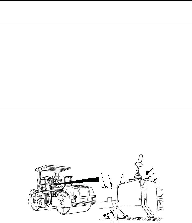
Remove two screws (Figure 1, Item 1) and washers (Figure 1, Item 5) from operator station (Figure 1, Item 4).
2.
Remove seven screws (Figure 1, Item 1) and washers (Figure 1, Item 2) from operator station
(Figure 1, Item 4).
3.
Lift panel assembly (Figure 1, Item 3) and pull away from operator station (Figure 1, Item 4).
1
3
2
1
2
4
5
1
M0865SWR
Figure 1.
Drum Select Switch Removal.
03/15/2011Rel(1.8)root(maintwp)wpno(M00096)