
TM 5-3895-379-23-1
0157
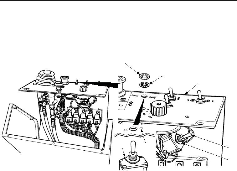
INSTALLATION - Continued
NOTE
Tab of ring (Figure 5, Item 7) must fit in notch (Figure 5, Item 6) in panel assembly to properly
align switch in panel assembly.
3.
Install water spray switch (Figure 5, Item 4) on panel assembly (Figure 5, Item 3) with new lockwasher
(Figure 5, Item 5), ring (Figure 5, Item 2), and nut (Figure 5, Item 1).
1
2
3
7
6
4
5
VIEW FROM DRIVER'S SEAT
M1244SWR
Figure 5. Water Spray Switch Installation.
03/15/2011Rel(1.8)root(maintwp)wpno(M00095)