
TM 5-3895-379-23-1
0157
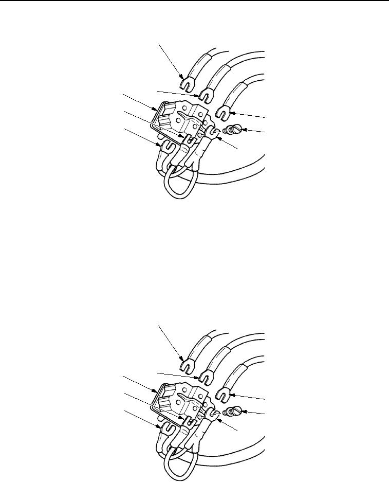
REMOVAL - Continued
1
8
7
6
2
5
3
4
M0863SWR
Figure 3. Water Spray Switch Removal.
END OF TASK
INSTALLATION
1.
Install three wires (Figure 4, Items 4, 5, and 6) on water spray switch (Figure 4, Item 7) with three screws
(Figure 4, Item 3).
2.
Install three wires (Figure 4, Items 1, 2, and 8) on water spray switch (Figure 4, Item 7) with three screws
(Figure 4, Item 3).
1
8
7
6
2
5
3
4
M1245SWR
Figure 4.
Water Spray Switch Installation.
03/15/2011Rel(1.8)root(maintwp)wpno(M00095)