
TM 5-3895-379-23-1
0156
REMOVAL - Continued
NOTE
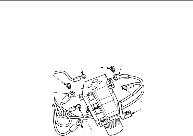
Tag and mark all wires prior to removal.
7.
Loosen two screw assemblies (Figure 3, Item 1) and remove two wires (Figure 3, Items 3 and 4) from parking
brake switch (Figure 3, Item 5).
8.
Loosen four screw assemblies (Figure 3, Item 1) and remove four wires (Figure 3, Items 2, 6, 7, and 8) from
parking brake switch (Figure 3, Item 5).
3
2
1
1
8
4
5
7
6
M0859SWR
Figure 3. Parking Brake Switch Removal.
END OF TASK
INSTALLATION
1.
Install four wires (Figure 4, Items 2, 6, 7, and 8) in parking brake switch (Figure 4, Item 5) and tighten four
screw assemblies (Figure 4, Item 1).
2.
Install two wires (Figure 4, Items 3 and 4) in parking brake switch (Figure 4, Item 5) and tighten two screws
assemblies (Figure 4, Item 1).
03/15/2011Rel(1.8)root(maintwp)wpno(M00094)