
TM 5-3895-379-23-1
0152
INSTALLATION - Continued
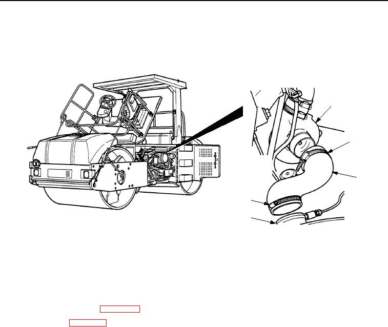
8.
Install hose (Figure 8, Item 3) and two clamps (Figure 8, Item 2) on air cleaner assembly (Figure 8, Item 4)
and turbocharger (Figure 8, Item 1). Tighten clamps securely.
VIEW FROM REAR OF
AIR CLEANER ASSEMBLY
1
2
3
2
4
M0846SWR
Figure 8.
Starter Installation.
END OF TASK
FOLLOW-ON MAINTENANCE
1.
Connect battery cables. (WP 0192)
2.
Install muffler. (WP 0134)
3.
Lower operator platform assembly. (Volume 2, WP 0235)
END OF TASK
END OF WORK PACKAGE
0152-9/10 blank
03/15/2011Rel(1.8)root(maintwp)wpno(M00090)