• Home
  • Download PDF
  • Order CD-ROM
  • Order in Print
Figure 1. Low Idle Speed Adjustment.
LOW IDLE SPEED ADJUSTMENT - Continued

Technical Manual For Roller, Motorized, Vibrating Tandem Steel Drums - 1 Page Navigation
  704    705    706    707    708  709  710    711    712    713    714  
img
.
TM 5-3895-379-23-1
0132
ADJUSTMENT - Continued
1
2
M0604SWR
Figure 2.
Low Idle Speed Adjustment.
6.
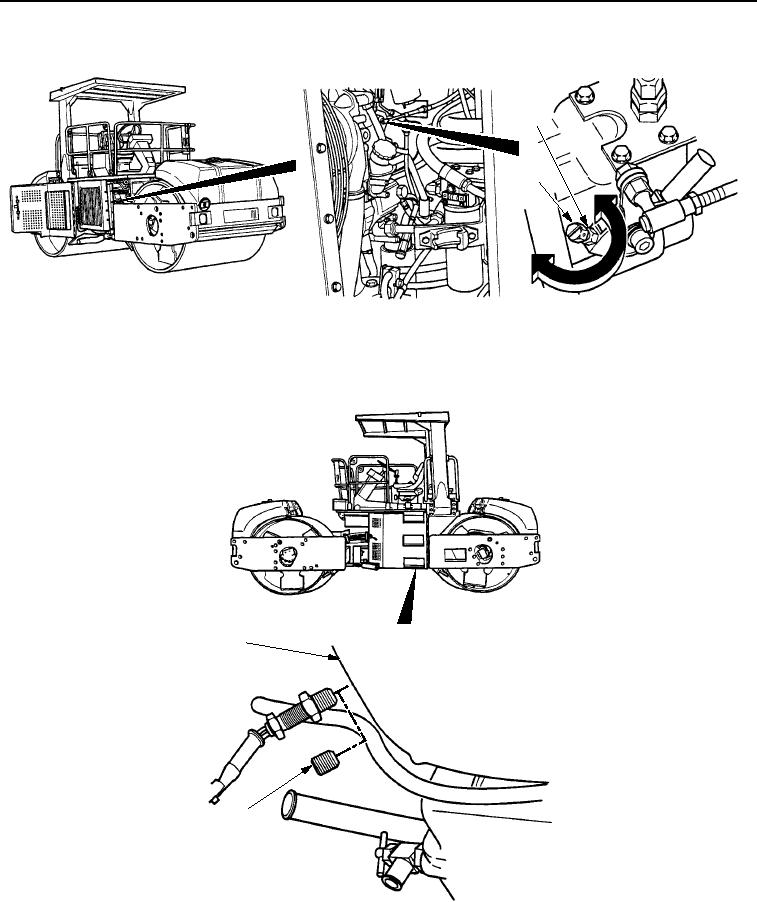
Remove Test Set and install plug (Figure 3, Item 2) in flywheel housing (Figure 3, Item 1).
1
VIEW LOOKING UP FROM
UNDER ROLLER
2
M0605SWR
Figure 3.
Low Idle Speed Adjustment.
END OF TASK
0132-3
03/15/2011Rel(1.8)root(maintwp)wpno(M00070)


Privacy Statement
Press Release
Contact

© Copyright Integrated Publishing, Inc.. All Rights Reserved.