
TM 5-3895-379-23-1
0132
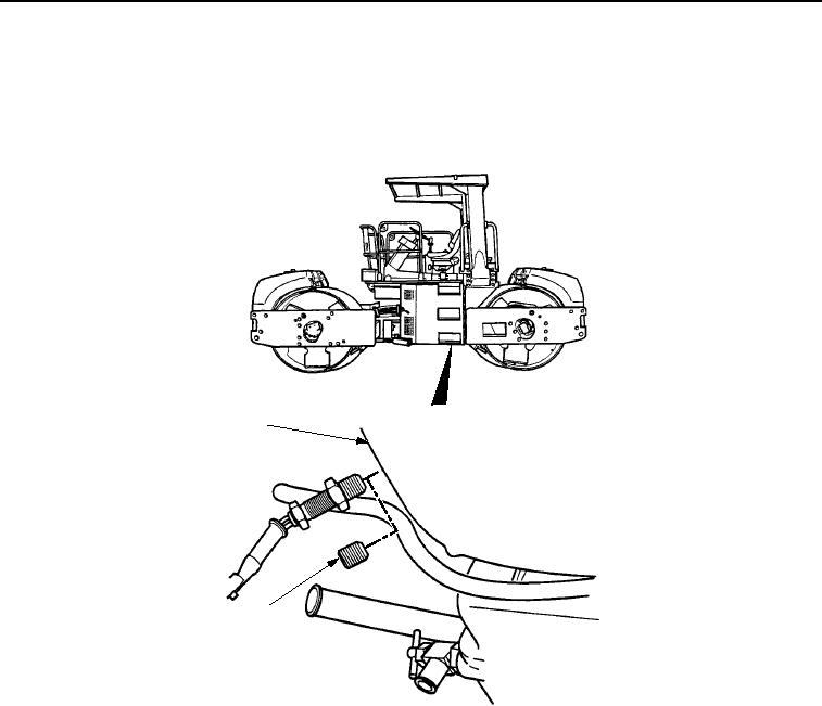
ADJUSTMENT
1.
Remove plug (Figure 1, Item 2) from flywheel housing (Figure 1, Item 1).
2.
Attach Test Set to flywheel housing (Figure 1, Item 1) per TM 9-4910-571-12&P, Test No. 10.
1
VIEW LOOKING UP FROM
UNDER ROLLER
2
M0603SWR
Figure 1. Low Idle Speed Adjustment.
3.
Start and run engine until it reaches normal operating temperature (TM 5-3895-379-10).
NOTE
Engine low idle speed is 1075 to 1125 rpm.
Turning adjustment screw clockwise increases engine speed. Turning adjustment screw
to the left decreases engine speed.
Throttle control must be set at the lowest speed position (pushed down) before adjusting
engine low idle speed.
4.
Loosen locknut (Figure 2, Item 1) and turn screw (Figure 2, Item 2) to adjust idle speed. Use Test Set, Test
No. 10 to monitor idle speed (TM 9-4910-571-12&P).
5.
When idle speed of 1075 to 1125 rpm is obtained, hold screw (Figure 2, Item 2) in place and tighten locknut
(Figure 2, Item 1).
03/15/2011Rel(1.8)root(maintwp)wpno(M00070)