
TM 5-3895-379-23-1
0130
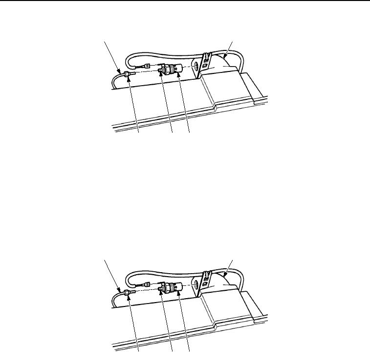
REMOVAL - Continued
1
2
5
4
3
M0584SWR
Figure 2.
Cold Start Heater Removal.
END OF TASK
INSTALLATION
1.
Install cold start heater (Figure 3, Item 3) into intake manifold elbow (Figure 3, Item 2). Tighten
to 204-337 lb-in. (23-38 Nm).
2.
Install fuel line (Figure 3, Item 1) into cold start heater nipple (Figure 3, Item 4) and tighten nut
(Figure 3, Item 5) to 35-71 lb-ft (47-96 Nm).
1
2
5
4
3
M1110SWR
Figure 3. Cold Start Heater Installation.
03/15/2011Rel(1.8)root(maintwp)wpno(M00068)