
TM 5-3895-379-23-1
0125
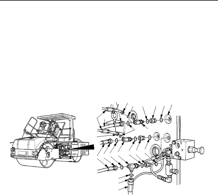
TANK INSTALLATION - Continued
CAUTION
Apply sealing compound to threads of all fittings and connections prior to installation. Failure
to do so can result in fuel and hydraulic leaks, equipment damage and failure.
20.
Install three new O-rings (Figure 30, Item 6) and boss reducers (Figure 30, Item 5) on fuel/hydraulic oil tank
(Figure 30, Item 7).
21.
Install three new O-rings (Figure 30, Item 4) and tees (Figure 30, Item 8) on three boss reducers
(Figure 30, Item 5).
22.
Install six new preformed packings (Figure 30, Item 3) and three hose assemblies (Figure 30, Item 9) on tees
(Figure 30, Item 8). Tighten nuts (Figure 30, Item 2).
23.
Install three new preformed packings (Figure 30, Item 3) and hose assemblies (Figure 30, Item 10) on tees
(Figure 30, Item 8). Tighten nuts (Figure 30, Item 1).
1
2
7
6
5
4
3
10
9
8
3
2
6
5
4
8
3
1
10
3
2
9
M0540SWR
Figure 30. Fuel/Hydraulic Oil Tank Installation.
24.
Install hydraulic oil temperature sensor (Figure 31, Item 1) in fuel/hydraulic oil tank (Figure 31, Item 4). Tighten
sensor to 310-399 lb-in. (35-45 Nm).
25.
Install two wires (Figure 31, Item 2) on hydraulic oil temperature sensor (Figure 31, Item 1) and tighten two
screws (Figure 31, Item 3) to 7-11 lb-in. (0.8-1.2 Nm).
03/15/2011Rel(1.8)root(maintwp)wpno(M00063)