
TM 5-3895-379-23-1
0125
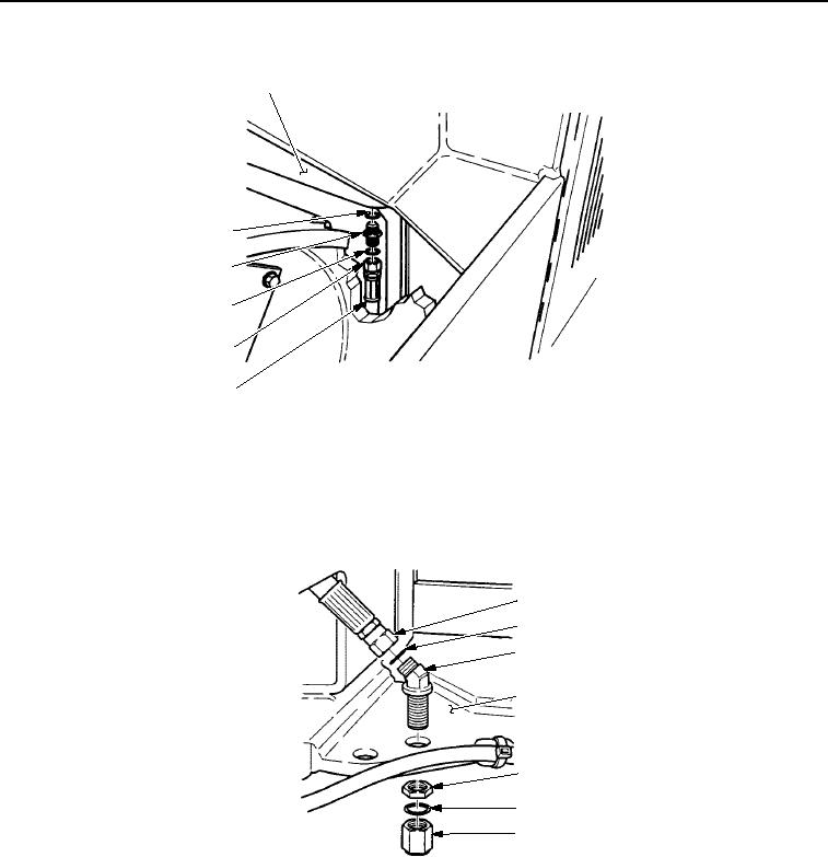
DRAIN LINES INSTALLATION - Continued
1
6
5
4
3
2
M0547SWR
Figure 37.
Drain Lines Installation.
8.
Install new O-ring (Figure 38, Item 2) and elbow (Figure 38, Item 3) on hose assembly (Figure 38, Item 1).
9.
Install hose assembly (Figure 38, Item 1) on frame assembly (Figure 38, Item 4) with nut (Figure 38, Item 5).
10.
Install new O-ring (Figure 38, Item 2) and fuel drain cap (Figure 38, Item 6) on hose assembly
(Figure 38, Item 1).
1
2
3
4
5
2
6
M0548SWR
Figure 38.
Drain Lines Installation.
END OF TASK
03/15/2011Rel(1.8)root(maintwp)wpno(M00063)