
TM 5-3895-379-23-1
0125
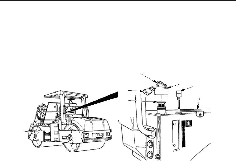
TANK INSTALLATION - Continued
9.
Apply sealant to threads of vent (Figure 25, Item 3) and install vent on fuel/hydraulic oil tank
(Figure 25, Item 4).
10.
Install strainer (Figure 25, Item 5) into fuel/hydraulic oil tank (Figure 25, Item 4).
11.
Lift lever (Figure 25, Item 1) and turn hydraulic oil cap (Figure 25, Item 2) clockwise until cap is secure on fuel/
hydraulic oil tank (Figure 25, Item 4).
12.
Install lock (Figure 25, Item 6) on hydraulic oil cap (Figure 25, Item 2).
1
2
3
6
4
5
M0535SWR
Figure 25. Fuel/Hydraulic Oil Tank Installation.
NOTE
Ensure hydraulic oil level indicator is installed with HIGH readable at the top of the indicator
and LOW readable at the bottom of the indicator.
13.
Install two washers (Figure 26, Item 5), four new preformed packings (Figure 26, Item 2), and hydraulic oil level
indicator (Figure 26, Item 4) on fuel/hydraulic oil tank (Figure 26, Item 1) using two screws
(Figure 26, Item 3).
03/15/2011Rel(1.8)root(maintwp)wpno(M00063)