
TM 5-3895-379-23-1
0125
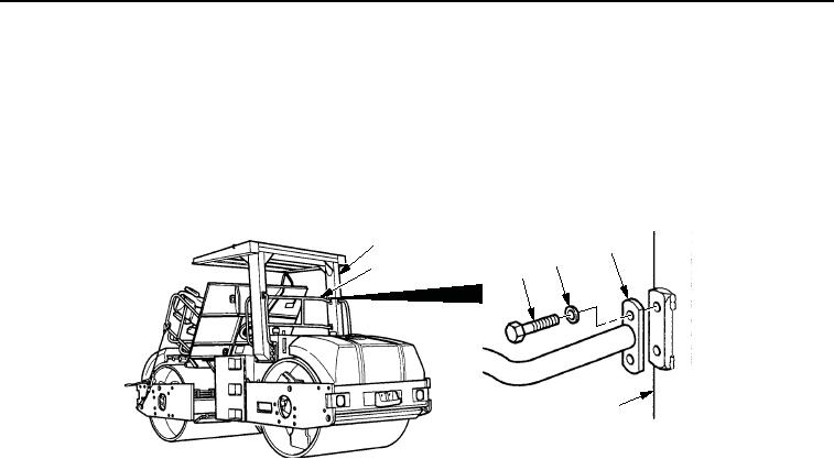
TANK INSTALLATION - Continued
15.
For the CB534C Roller, install rear handrail assembly (Figure 28, Item 2) on ROPS (Figure 28, Item 1) using
four washers (Figure 28, Item 4) and screw (Figure 28, Item 3). Tighten screws 33-47 lb-ft (45-64 Nm).
1
2
4
2
3
1
M0538SWR
Figure 28. Fuel/Hydraulic Oil Tank Installation.
16.
Install suction strainer (Figure 29, Item 7) in fuel/hydraulic oil tank (Figure 29, Item 6).
17.
Install new O-ring (Figure 29, Item 5) and elbow (Figure 29, Item 4) on fuel/hydraulic oil tank
(Figure 29, Item 6).
18.
Install new O-ring (Figure 29, Item 5) and elbow (Figure 29, Item 4) on suction strainer (Figure 29, Item 7).
19.
Install two new preformed packings (Figure 29, Item 3) and hose assemblies (Figure 29, Item 1) on two elbows
(Figure 29, Item 4) and tighten two nuts (Figure 29, Item 2).
03/15/2011Rel(1.8)root(maintwp)wpno(M00063)