
TM 5-3895-379-23-1
0119
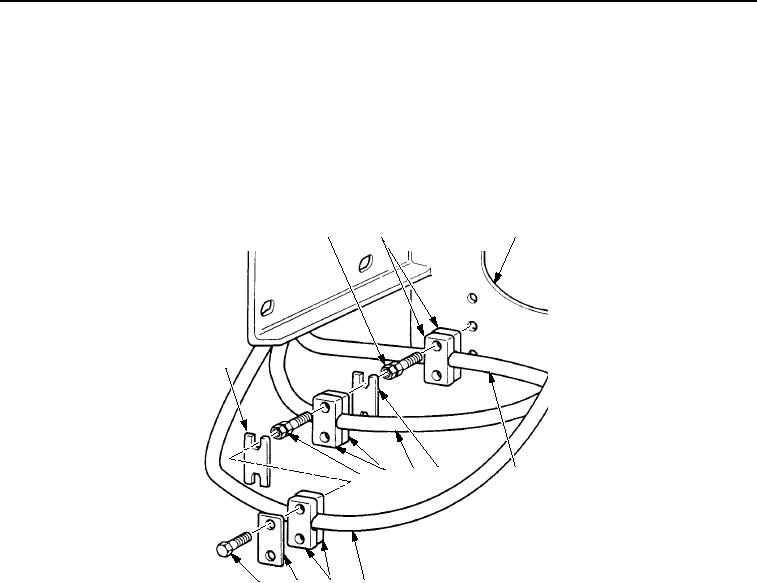
INSTALLATION - Continued
6.
Position hose (Figure 9, Item 5) in clamp (Figure 9, Item 3) and install clamp on mounting bracket
(Figure 9, Item 4) with two screws (Figure 9, Item 2) and plate (Figure 9, Item 6).
7.
Position hose (Figure 9, Item 7) in clamp (Figure 9, Item 8) and install clamp on two screws (Figure 9, Item 2)
with two screws (Figure 9, Item 9) and plate (Figure 9, Item 1).
8.
Position hose (Figure 9, Item 10) in clamp (Figure 9, Item 11) and install clamp and plate (Figure 9, Item 12)
on two screws (Figure 9, Item 9) with two screws (Figure 9, Item 13).
2
3
4
1
9
8
7
6
5
13
12
11
10
M1071SWR
Figure 9. Air Cleaner Support Assembly Installation.
9.
Position two hoses (Figure 10, Items 5 and 6) in clamp (Figure 10, Item 3) and install clamp on mounting
bracket (Figure 10, Item 4) with screw (Figure 10, Item 2) and plate (Figure 10, Item 1).
10.
Position two hoses (Figure 10, Items 7 and 8) in clamp (Figure 10, Item 9) and install clamp and plate
(Figure 10, Item 10) on screw (Figure 10, Item 2) with screw (Figure 10, Item 11).
03/15/2011Rel(1.8)root(maintwp)wpno(M00057)