
TM 5-3895-379-23-1
0119
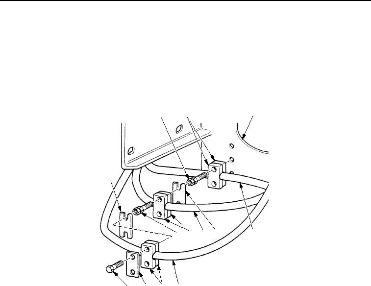
REMOVAL - Continued
3.
Remove two screws (Figure 2, Item 12), plate (Figure 2, Item 11), clamp (Figure 2, Item 10), and hose
(Figure 2, Item 9) from two screws (Figure 2, Item 8).
4.
Remove plate (Figure 2, Item 13), two screws (Figure 2, Item 8), clamp (Figure 2, Item 7), and hose
(Figure 2, Item 6) from two screws (Figure 2, Item 1).
5.
Remove plate (Figure 2, Item 5), two screws (Figure 2, Item 1), clamp (Figure 2, Item 2), and hose
(Figure 2, Item 4) from mounting bracket (Figure 2, Item 3).
1
2
3
13
8
7
6
5
4
12
11
10
9
M0485SWR
Figure 2. Air Cleaner Support Assembly Removal.
NOTE
Remove electrical tiedown straps from wiring harness as required. Discard electrical tiedown
straps.
6.
Remove wiring harness (Figure 3, Item 4) from air cleaner support assembly (Figure 3, Item 3).
NOTE
Do not remove hydraulic lines.
7.
Remove two nuts (Figure 3, Item 2), washers (Figure 3, Item 1), screws (Figure 3, Item 5), washers
(Figure 3, Item 6), and brake control valve (Figure 3, Item 7) from mounting bracket (Figure 3, Item 3).
03/15/2011Rel(1.8)root(maintwp)wpno(M00057)