
TM 5-3895-379-23-1
0096
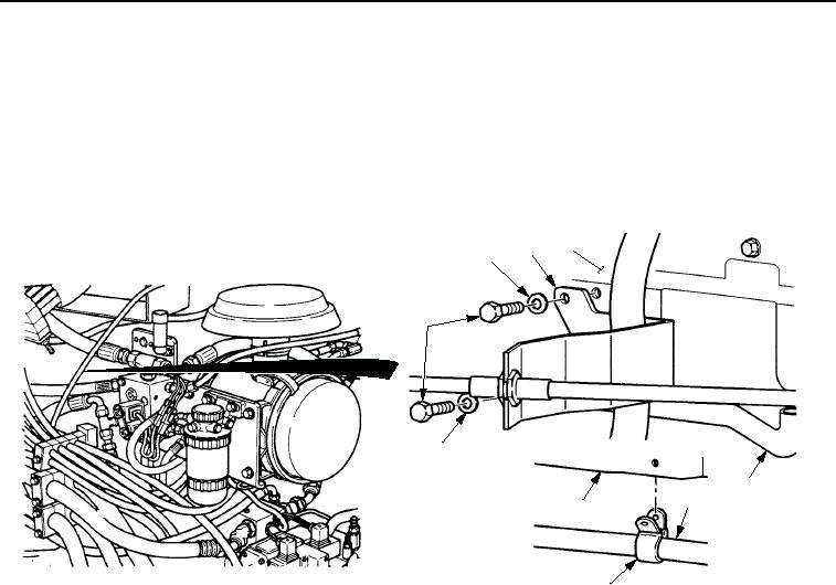
INSTALLATION
1.
Place clamp (Figure 4, Item 5) on tube (Figure 4, Item 4).
2.
Install hose (Figure 4, Item 4), clamp (Figure 4, Item 5), and throttle cable bracket (Figure 4, Item 2) on engine
block (Figure 4, Item 3) with two washers (Figure 4, Item 1) and screws (Figure 4, Item 6). Tighten screws to
15-25 lb-ft (20-34 Nm).
3
2
1
6
1
4
4
2
5
M0101SWR
Figure 4. Engine Oil Cooler Lines and Fittings Installation.
3.
Place clamp (Figure 5, Item 4) on hose (Figure 5, Item 5).
4.
Install hose (Figure 5, Item 5) on tube (Figure 5, Item 3) and tighten clamp (Figure 5, Item 4).
5.
Place clamp (Figure 5, Item 1) on hose (Figure 5, Item 5).
6.
Install hose (Figure 5, Item 5) on adapter (Figure 5, Item 2) and tighten clamp (Figure 5, Item 1).
03/15/2011Rel(1.8)root(maintwp)wpno(M00035)