
TM 5-3895-379-23-1
0080
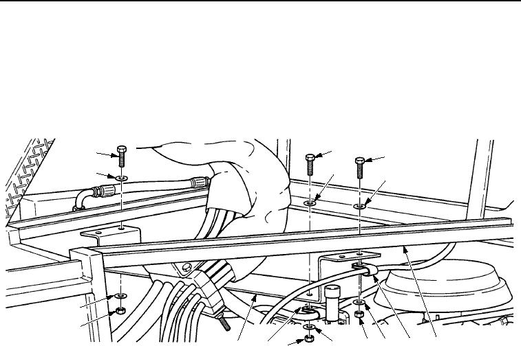
INSTALLATION - Continued
7.
Install upper cross brace (Figure 6, Item 10) on upper frame assembly (Figure 6, Item 5) with four washers
(Figure 6, Item 4), screws (Figure 6, Item 1), two clips (Figure 6, Item 6), four washers (Figure 6, Item 4), and
nuts (Figure 6, Item 7).
8.
For CB534B Roller, install clip (Figure 6, Item 9) on upper cross brace (Figure 6, Item 10) with washer
(Figure 6, Item 3), screw (Figure 6, Item 2), washer (Figure 6, Item 3), and nut (Figure 6, Item 8).
2
1
1
3
4
4
4
7
5
6
4
3
7
10
8
9
M0058SWR
Figure 6. Front Engine Mount Installation.
END OF TASK
FOLLOW-ON MAINTENANCE
1.
Install hydraulic oil cooler. (Volume 2, WP 0260)
2.
Lower operator platform. (Volume 2, WP 0235)
3.
Start engine and check for leaks. (TM 5-3895-379-10)
END OF TASK
END OF WORK PACKAGE
03/15/2011Rel(1.8)root(maintwp)wpno(M00019)