PNEUMATIC ISOLATOR (TIRE AND WHEEL) REMOVAL
FOR REPAIR OR CHANGE (Figures 21 thru 27)
The pneumatic Isolators (tire and wheel) can be removed
without removing the roller from the roller frame. For the
purpose of describing the roller sides - the hydraulic motor
side is the drive end and the opposite side is the driven
end.
Repair should be made on a hard level surface. As a
safety measure, wedge block the traction tires, front and
back. Connect the steering lock link
1. Figure 21 Remove the roller frame side covers at the
drive and driven ends
2. Figure 21 Place hydraulic jacks or blocking under the
front and rear ends of the roller side frame being
FIGURE 22
repaired, where indicated with arrows. Apply just
enough upward pressure to keep the frame from
lowering
3. Deflate pneumatic Isolator (tire) at opposite side being
repaired to approximately 10 PSI (presuming the tire
being repaired is already deflated) This is to acquire
as much end play as possible to accomplish step 7
FIGURE 23
7.
Figure 26 Using a sizable pry bar, place pry bar
between roller frame and edge of roller on the side
being repaired and pry to force the roller frame away
from the roller as far as possible. This will permit
more clearance to remove the isolator.
FIGURE 21
8. Manipulate the Isolator up and out from the roller
frame NOTE The tire is keywayed to fit the key
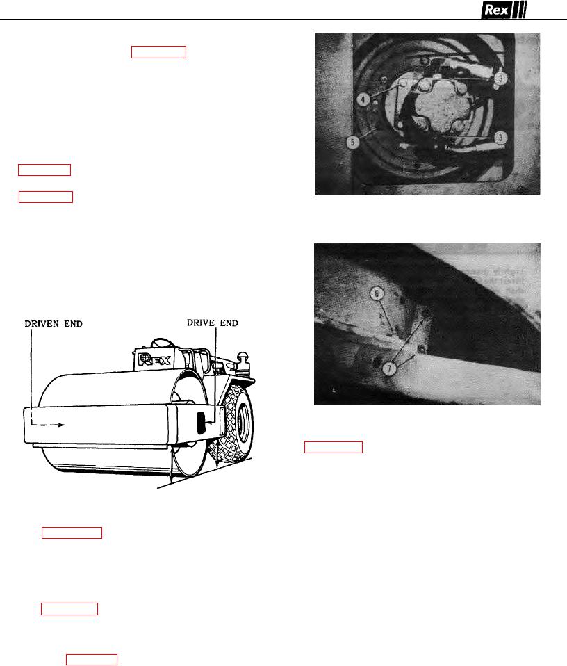
4. Figures 22 and 23 Drive End Remove the hose
welded to the upper isolator half In reassembly the
clamp holding the two high pressure hoses in place.
keyway in tire must line up and fit the key in isolator.
Loosen slightly (but do not remove the two hydraulic elbow 9. Repair or change tire in the conventional manner
fittings (3) threaded into motor). Remove four cap screws
(4) holding the motor to the motor and wheel mount Pull 10. Clean and inspect the interior of the isolator halves.
After inspection, should the non-slip material be loose
and swing out the motor from mounting frame.
or damaged, it should be replaced with new Interior
5. Figure 23 Remove two cap screws (6), one each
surfaces must be cleaned with a solvent and dry
side, holding Isolator cover half to roller frame. Remove
before application of new non-slip material.
four cap screws (7), two each side, holding the upper and
lower cover halves together, then remove upper cover half 11. Assembly is in reverse of above Add hydraulic oil to
reservoir as a result of oil lost at loose motor
6. Refer figure 22. Remove six cap screws (5)
connections.
30

