
SECTION 7
TRANSMISSION
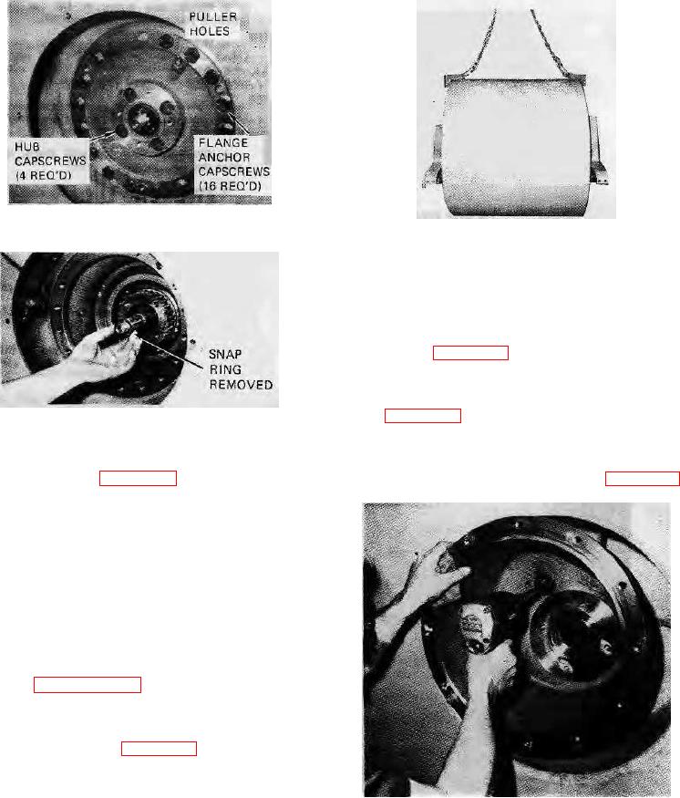
FIGURE 7-71.
FIGURE 7-73.
7-200. DISASSEMBLY OF MOTOR CARRIER.
a. Remove o-ring on outside of bearing carrier for
replacement. Remove bearing lock plate and shims.
Check flatness of lock plate with a straight edge. Replace
if deformed (see figure 7-75).
b. Lift off bearing carrier, upper bearing, and seal from
motor housing. Tag the bearing cone with its respective
cup (see figure 7-76).
FIGURE 7-72.
c. Inspect the bearings, cups and cones. Remove
drum out of the rear of the unit taking care not to damage
bearing from the carrier and replace if the rollers or cups
machined surfaces (see figure 7-73).
are worn, pitted or damaged in any way (see figure 7-77).
CAUTION:
Care must be taken not to damage
machined surfaces.
WARNING:
The drive drum is extremely heavy
(approximately 12,000 lbs.
(5,440 kg)
without ballast.) Caution personnel in area
to stand clear.
7-199. REMOVAL OF MOTOR CARRIER.
a. Complete the drive drum
removal procedure
presented in paragraph 7-198.
b. Remove the motor carrier-to-drum mounting
capscrews by turning the carrier and aligning the hole in
carrier with capscrews (see figure 7-74).
WARNING:
Support the motor carrier with hoist and
sling arrangement.
FIGURE 7-74.
c. Using the puller holes provided, pull the carrier and
lift from unit.
7-44.