
SECTION 7
TRANSMISSION
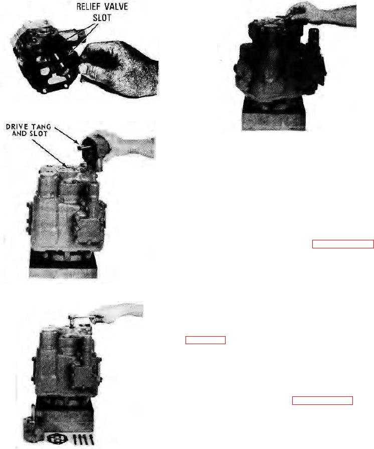
FIGURE 7-48.
FIGURE 7-51.
NOTE: Excessive tightening may distort the charge pump
and cause leakage or malfunction.
f.
Check oil level in the reservoir.
7-183. REPLACEMENT OF CHECK VALVES.
7-184. REMOVAL.
a. Remove the charge pump (see paragraph 7-181).
b. Using a drag link, unscrew check valve from end
cap (see figures 7-50 and 7-51).
NOTE: There are two check valves. It is advisable to
replace both check valves at the same time.
FIGURE 7-49.
7-185. INSTALLATION.
a. Prior to installation, inspect o-rings for damage (see
b. Apply a light coat of oil.
c. Install check valves and torque to 80-90 ft.-lbs.
(11.06-12.44 kg-m).
d. Install charge pump (see paragraph 7-182).
CAUTION: The valves must assemble below the face of
the end cap.
7-186.
REPLACEMENT OF BY-PASS VALVE AND
MOTOR MANIFOLD.
FIGURE 7-50.
7-38.