
SECTION 7
TRANSMISSION
prevent dirt from entering the transmission.
b. Place Direction-Throttle Bail in detonated
neutral position.
c. Adjust wire stop (A) at lower throttle crank for
CAUTION: Whenever a component of the hydrostatic
1/16 in. (1.59 mm) gap between swivel and wire stop.
system has been re- moved, the
d. Adjust position of upper throttle link (B) ball joint
transmission start-up procedure MUST be
in slot of throttle actuator arm (C) so that full stroke of
performed before the unit can be started,
throttle is obtained when Direction-Throttle Bail is
operated or returned to service.
stroked from stop to stop. LENGTHEN upper throttle link
(B) to reduce throttle stroke or SHORTEN link to
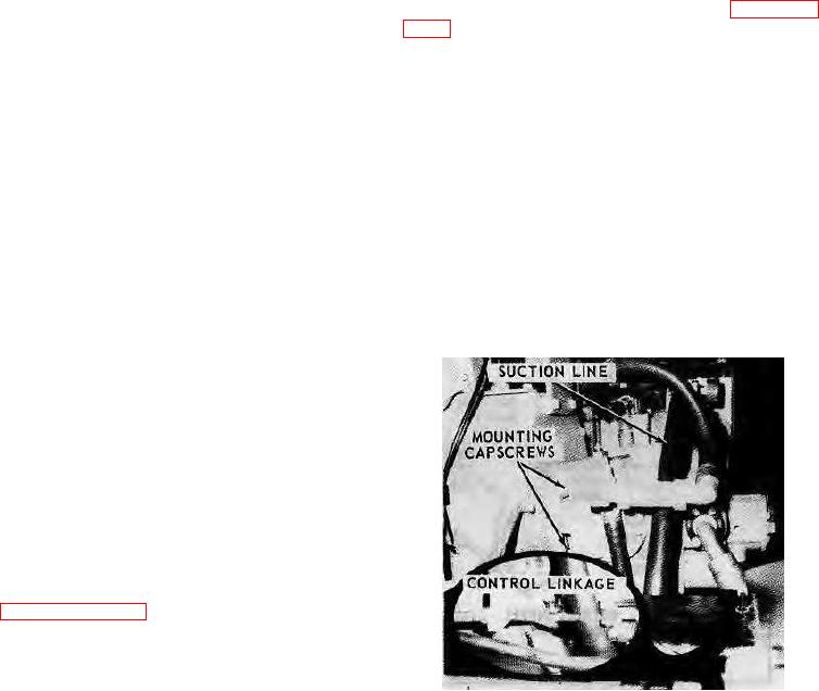
7-178. HYDROSTATIC PUMP REMOVAL (see figure
increase throttle stroke.
a. Remove the suction line at the filter and plug or
NOTE: Throttle stroke should be identical in forward
cap hose and fitting.
and reverse. Check for bent or binding linkage
b. Disconnect control linkage from servo control
if a problem exists.
lever.
e. Adjust friction nuts (D) so Direction Throttle Bail
c. Disconnect the hydraulic lines at the top of the
will stay in any position.
pump.
f. Adjust the neutral safety switch adjustment
d.
Disconnect the high-pressure lines from the
bracket (E) so that the switch will just barely be
pump end housing. Plug or cap all hoses and fittings.
activated when the Direction-Throttle Bail is in neutral
position.
WARNING: Use a hoist and sling arrangement to
support the weight of the pump.
7-174. TRANSMISSION REPAIR.
7-175. Should it become necessary to perform repairs to
e. Remove the capscrews securing the pump to
the Sundstrand transmission during the warranty period,
mount plate.
certain parts, components or kits may be replaced
f. Pull pump straight back and tilt shaft end of
without affecting or violating the warranty.
pump up enough to lift pump from unit.
7-176. The following parts, components or kits may be
replaced in the field as an assembly without affecting,
violating or voiding the transmission warranty:
a. Charge pump
b. Check valves
c. Motor manifold assembly
d. High-pressure relief valves
e. Displacement control valve (pump)
f. Pump or motor shaft seals
7-177. The proper procedures for replacement of the
above components are presented in the following
paragraphs.
NOTE: Unauthorized
repairs
to
transmission
components other than those listed in
paragraph 7-176 may void the warranty.
Contact Hyster Company before attempting to
perform repairs other than those presented in
this manual.
CAUTION: When working on all hydraulic equipment,
cleanliness is very important. Before
FIGURE 7-45.
removing any of the transmission
components, clean the immediate area to
7-36