TM 5-3895-383-24
Case Flushing
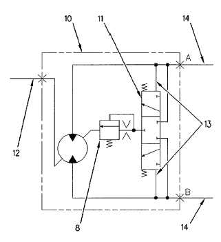
Illustration 34
Hydraulic Schematic For The Motor
(8) Flushing relief valve. (10) Motor housing. (11) Flushing
shuttle valve. (12) Line (drain to return manifold). (13) Pilot
passages. (14) Loop lines.
Lubrication for the internal moving parts is done with the
normal internal leakage oil. The case flushing and the cooling
of the pump and the motor is accomplished by the flushing
circuit.
The flushing circuit oil is supplied by the charge circuit. The
flushing of the vibratory pump is continuous. Case flushing of
the motor occurs during the pump stroke.
Oil enters the motor and oil exits the motor (10) through the
loop lines (14). The pilot oil from the loop lines (14) flows to
both ends of the shuttle spool (6). The flow is through the pilot
oil passages (13). The high pressure side of the circuit shifts
the shuttle spool (6). The shift of the shuttle spool allows the
low pressure oil of the loop lines (14) to flow through the
flushing relief valve (8). The oil flushes the motor housing (10)
and flows to the return manifold through line (12). The thermal
bypass valve directs the oil through the oil cooler or to the
hydraulic tank. The temperature of the oil will determine the
direction of the oil.
The charge pump supplies approximately 20 L/min (5.3 US
gpm). The charge pump replenishes normal leakage oil. The
remaining charge oil will dump in one of two places:
The relief valve
Flow through the flushing valve
In order to flush the motor housing, the flow rate of the oil in
the flushing relief valve (8) must be 4.9 L/min (1.3 US gpm).
11-34


