TM 5-3895-383-24
Variable Frequency Electrical
Control
(If Equipped)
SMCS Code: 6606
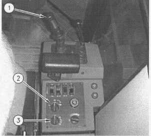
Illustration 27
Control Console
(1) Vibratory ON/OFF control. (2) Vibratory amplitude control.
(3) Variable vibration control knob.
The variable vibratory system is an option. The functions of
the vibratory ON/OFF control (1) and the vibratory amplitude
control (2) are identical to the dual amplitude system.
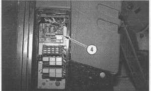
Illustration 28
Control Console
(4) Variable frequency controller.
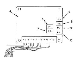
Illustration 29
Variable Frequency Controller Potentiometers
(4) Variable frequency controller.
(5) Ramp time potentiometer.
(6) "P5" Low amplitude-minimum frequency potentiometer.
(7) Ramp time potentiometer.
(8) "P6 High amplitude-minimum frequency potentiometer.
(9) "P3" Low amplitude-maximum frequency potentiometer.
(10) "P4" High amplitude-maximum frequency potentiometer.
The main differences between the variable frequency system
and the dual amplitude system are the variable frequency
controller (4) and the rheostat.
Variable vibration control knob (3) is connected to the rheostat.
The rheostat controls the hydraulic system for the drum
vibration. The rheostat will vary the amperage to the control
valve on the vibratory pump.
"P1" and "P2" ramp time potentiometer (5) and (7) control the
amount of time so that the pump control can receive the
correct amount of amperage. The ramp time potentiometer
allow the amperage to increase from zero to the maximum
amperage in two seconds.
Place the vibratory amplitude control (2) in the LOW
AMPLITUDE position and turn the variable vibration control
knob (3) to a full counterclockwise position. The position
enables the "P5" potentiometer (6) to control the amperage to
the pump control. The position enables the "P5" potentiometer
(6) to maintain the lower limit of vibration per minute (VPM) at
1400 50 VPM.
11-30