TM 5-3895-383-24
Circuit Operation
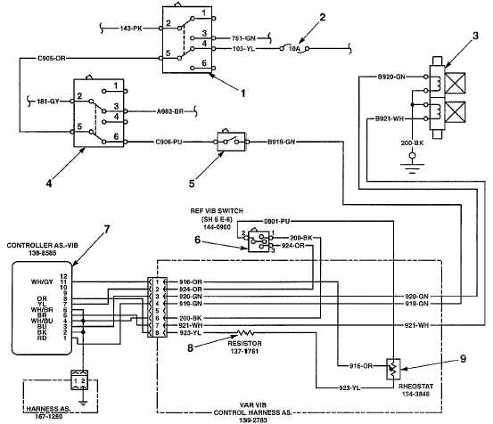
Illustration 43
Vibratory Circuit Operation
(1) Propel range switch. (2) Fuse. (3) Vibratory control solenoids. (4) Throttle switch. (5) Vibratory on/off switch. (6) Vibration control
switch. (7) Frequency control/adjustment card. (8) Resistor. (9) Variable frequency control.
When the key start switch is in the ON position, the main relay
is closed and system voltage is present in wire 112-PU-10.
The system voltage is present in wire 103-YL when fuse (2) is
okay.
If the propel range switch (1) is in LOW position, voltage will be
present at wire C905-OR and throttle switch (4). The throttle
switch (4) must be in HIGH position so that the voltage will be
present at wire C906-PU.
When the vibration control switch (5) is pressed, the switch will
close. The switch will create a path through wire B919-GN to
the switch on the vibration control switch (6). If the vibration
control switch is in the center position, the vibratory system is
not activated, or OFF. If the vibration control switch is in the
LOW position, a path to wire 200-BK is created, and the
frequency control/adjustment card controls the circuit to allow
only low amplitude signal to the solenoids (3). If the vibration
control switch is in the HIGH position, a path to wire 924-OR is
created allowing the high amplitude signal to reach the
solenoids. The variable frequency control (9) is a rheostat that
controls the current flow that determines speed at which the
solenoids react to create the speed of vibration.
11-39