TM 5-3895-383-24
Crankcase breather (23) allows blow-by gases from the
cylinders to escape from the crankcase. This prevents
pressure from building up that could cause seals and gaskets
to leak.
Oil pressure to the camshaft and main bearings should be
checked on the side of the cylinder block at oil gallery plug
(25).
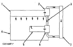
Cooling System
Cooling System Schematic
(1) Cylinder head. 2) Water temperature regulator housing.
(3) Bypass hose. (4) Cylinder block. (5) Oil cooler. (6) Water
pump. (7) Radiator.
Water pump (6) is located on the right side of the cylinder
block. It is belt driven from the crankshaft pulley. Coolant from
the bottom of the radiator is pulled into the bottom inlet of the
pump by impeller rotation. The coolant exits the back of the
pump directly into the oil cooler cavity of the block.
All the coolant passes through the core of the oil cooler and
enters the internal water manifold of the cylinder block. The
manifold distributes the coolant to water jackets around the
cylinder walls.
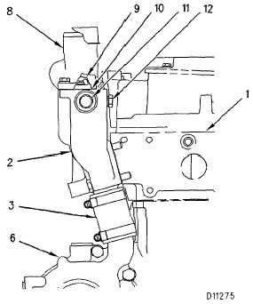
Water Lines Group
(1) Cylinder head. (2) Water temperature regulator housing.
(3) Bypass hose. (6) Water pup. (8) Outlet (to radiator). (9)
Water temperature regulator (shown partially open). (10) Air
vent valve (located in flange of thermostat). (11) Water return
from air compressor (if equipped). (12) Port or pump outlet
pressure (for engine diagnosis).
NOTE:
Some commercial engines have a bypass hole
and is used on engines which use a Caterpillar
supplied automotive type radiator only.
NOTE:
Later thermostats have an air vent valve. The air
vent valve allows air to escape from the cooling
system while coolant is added.
6-21