TM 5-3895-383-24
The two piece pistons consist of an alloy steel crown
connected to an aluminum skirt by the piston pin. Piston
cooling jets in the cylinder block spray oil to the underside of
the piston crown to cool the piston. All three rings are located
in grooves in the piston crown. Holes in the oil control (lower)
ring groove allow oil to return to the crankcase.
The connecting rod has a taper on the pin bore end. This
gives the rod and piston more strength in the areas with the
most load. Two bolts hold the rod cap to the rod. This design
keeps the rod width to a minimum, so that the rod can be
removed through the cylinder.
Crankshaft
The crankshaft changes the combustion forces in the cylinder
into usable rotating torque which powers the equipment. A
vibration damper is used at the front of the crankshaft to
reduce torsional vibrations (twist on the crankshaft) that can
cause damage to the engine.
The crankshaft drives a group of gears on the front of the
engine. The gear group drives the oil pump, camshaft,
governor, and the gear driven air compressor and/or power
steering pump. In addition to this, the front belt pulleys on the
crankshaft drive the radiator fan, water pump, alternator and
freon compressor.
Hydrodynamic seals are used at both ends of the crankshaft to
control oil leakage. The hydrodynamic grooves in the seal lip
move lubrication oil back into the crankcase as the crankshaft
turns. The front seal is located in the front housing. The rear
seal is installed in the flywheel housing.
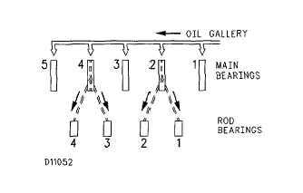
Schematic Of Oil passages In Crankshaft (4 cylinder)
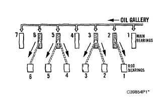
Schematic Of Oil Passages In Crankshaft (6 cylinder)
Pressure oil is supplied to all main bearings through drilled
holes in the webs of the cylinder block. The oil then flows
through drilled holes in the crankshaft to provide oil to the
connecting rod bearings. The crankshaft is held in place by
seven main bearings. A thrust main bearing next to the rear
main bearing controls the end play of the crankshaft.
6-24


