TM 5-3895-383-24
Maximum rpm of the turbocharger is controlled by the
wastegate (which is controlled by the boost pressure), the fuel
setting, the high idle rpm setting and the height above sea level
at which the engine is operated.
NOTICE
If the high idle rpm or the fuel setting is higher than given
in the TMI (Technical Marketing Information) Governor
Bench Performance Data, (for the height above sea level at
which the engine is operated), there can be damage to
engine or turbocharger parts. Damage will result when
increased heat and/or friction due to the higher engine
output goes beyond the engine cooling and lubrication
systems abilities. A mechanic that has the proper training
is the only one to make the adjustment of fuel setting and
high idle rpm setting.
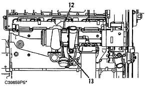
Turbocharger Oil Lines
(12) Oil inlet line [to oil inlet port (4)]. (13) Oil drain line [from
oil outlet port (8)].
The bearings (7) in the turbocharger use engine oil under
pressure for lubrication. The oil is sent through oil inlet line
(12) to inlet port (4) at the top, then goes through passages in
the center section for lubrication of the bearings. Then the oil
goes out oil outlet port (8) at the bottom and back to the engine
block through drain line (13).
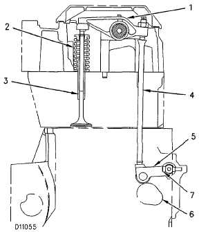
Valve System Components
Valve System Components
(Typical example for floating button)
(1) Rocker arm. (2) Spring. (3) Valve (4) Push rod. (5) Lifter.
(6) Camshaft lobe. (7) Bolt which holds lifter shaft to the side
cover.
The valve system components control the flow of inlet air and
exhaust gases into and out of the cylinders during engine
operation.
The crankshaft gear drives the camshaft gear through an idler.
The camshaft must be timed to the crankshaft to get the
correct relation between piston and valve movement.
The camshafts have three cam lobes for each cylinder. Two
lobes operate the valves (one intake and one exhaust) and one
operates the fuel injector. As the camshaft turns, lobes (6) on
the camshaft cause the lifters (5) to move push rods (4) up and
down. Upward movement of the push rods against rocker
arms (1) results in downward movement (opening) of valves
(3).
Each cylinder has one intake and one exhaust valve. Valve
springs (2) close the valves when the lifters move down.
6-17