TM 5-3895-383-24
Air Inlet Heater
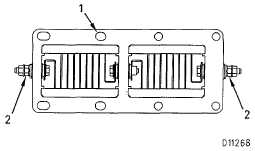
Section View Heater Assembly
(Inlet Manifold)
(1)
Heater assembly.
(2)
Tighten nuts to a torque of................................13 1 Nm
(10 ± 1 lb-ft)
NOTE:
When assembling air inlet heater to intake
manifold and air inlet elbow, clean air inlet heater
joint faces with solvent. Apply 6V1541 Quick Cure
Primer to joint faces. Allow primer to air dry three
to five minutes minimum. Apply 1 U8846 Gasket
Maker to joint face and spread uniformly. Heater
must be assembled and tightened within ten
minutes.
6I396
12 VAC, 1000 W................................................................92 ± 9.2 A
6I4753
22 VAC, 1900 W................................................................86 8.6 A
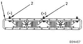
Section View Of Heater Assembly
(Inlet Manifold)
107-0178
12 VAC, 1000W.................................................................92 ± 9.2 A
107-9652
22 VAC, 2200 W............................................................. 98 ± 14.7 A
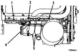
Ether Starting Aid
For dual tube air inlet.
(1)
Air inlet manifold.
(2)
Atomizer for rear three cylinders. Minimum seating
torque ........................................................2.8 Nm (25 lb-in)
(3)
Atomizer for front three cylinders. Minimum seating
torque .......................................................2.8 Nm (25 lb-in)
NOTE:
Two marks (180 degrees apart) indicate the orifice
spray direction. These marks must be pointed to
the front and the rear of the engine to avoid
spraying ether onto the inlet air heater element.
(4)
Heater group.
(5)
Air inlet elbow (dual tube air inlet).
Wiring Group (Air Inlet Heater)
NOTE:
Wiring and control systems vary for different air
inlet heater groups and is dependent on engine
application. Refer to parts book for wiring details.
5-44