TM 5-3895-383-24
Fuel System (Type I)
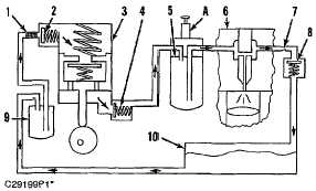
Fuel System Schematic
(1) Screen (if equipped). (2) Inlet check valve. (3) Fuel
transfer pump (integral with governor). (4) Outlet check valve.
(5) Fuel filter. (6) Cylinder head. (7) Pressure regulating
orifice. (8) Check valve. (9) Primary fuel filter (if equipped).
(10)
Fuel
tank.
(A)
Fuel
priming
pump
(equipped).
Fuel from the fuel tank is pulled through an in-line screen (1)
by fuel transfer pump (3). The fuel transfer pump is integral
with the governor. Fuel is sent from the fuel transfer pump
through fuel filter (5) and to a drilled passage in cylinder head
(6). The drilled passage in the cylinder head intersects a
gallery around each unit injector to provide a continuous flow of
fuel to all injectors.
When there is air on the inlet side of the fuel system, fuel
priming pump (A) (if equipped) may be used to fill the fuel filter
and fuel gallery (in the cylinder head) from the fuel tank before
the engine is started. When the priming pump is used, check
valves located in the fuel priming pump. Control the movement
of fuel through the low pressure side of the system which
removes air from the fuel lines and components back into the
fuel tank.
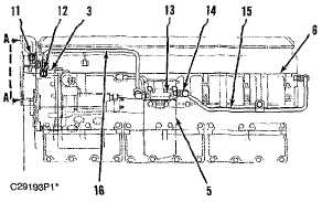
Fuel Filter Lines Group
(3) Fuel transfer pump (integral with governor). (5) Fuel filter.
(6) Cylinder head. (11) Fuel outlet port (to tank). (12) Fuel
inlet port (to fuel transfer pump). (13) Fuel filter base. (14)
Filtered fuel pressure tap. (15) Tube assembly (from fuel filter
base to cylinder head fuel gallery in cylinder head). (16) Tube
assembly (from transfer pump to fuel filter base).
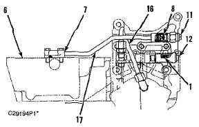
Fuel Filter Lines Group (View A-A)
(1) Screen. (6) Cylinder head. (7) Pressure regulating orifice.
(8) Check valve. (11) Fuel outlet port (to tank). (12) Fuel inlet
port (to fuel transfer pump). (16) Tube assembly (from transfer
pump to fuel filter base). (17) Tube assembly (return to tank
from fuel passage in cylinder head).
6-6