TM 5-3895-383-24
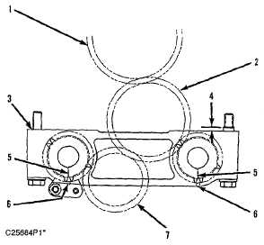
Balancer Group
3114 Engine Only
Front View
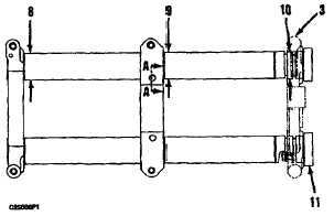
Top View
(1)
Crankshaft gear.
(2)
Oil pump idler gear.
(3)
Oil pump housing.
(4)
Dimension from top surface of supports to top of
sleeves ...................................... 5.0 ± 0.5 mm (.20 ± .02 in)
(5)
Align timing marks on balancer gears (10) with holes (5)
in oil pump body when No. 1 cylinder is at top center
position.
(6)
Marks on oil pump body.
(7)
Oil pump drive gear.
(8)
Diameter of bores in rear
support ...................................................48.540 0.025 mm
..................................................................(1.9110 ± .0010 in)
Diameter of balancer shafts at rear
support .....................48.40 ± 0.02 mm (1.9055 ± .0008 in)
(9)
Diameter of bores for bearings in center
support .....................51.54 ± 0.02 mm (2.0291 ± .0008 in)
Bearings must be flush with the forward surface of the
support.
Diameter of balancer shafts at center
support .....................48.40 ± 0.02 mm (1.9055 ± .0008 in)
(10)
Diameter of bores in oil pump housing for balancer
shafts.................48.540 ± 0.025 mm (1.9110 ± 0.0010 in)
Diameter of balancer shafts at oil pump
housing ....................48.40 ± 0.02 mm (1.9055 ± .0008 in)
(11)
Balancer gears: Maximum temperature of gears for
shrinking on balancer shafts (do not use a torch)
...........................................................................232C(450F)
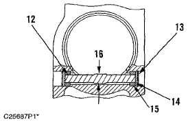
View A-A
(12)
Diameter of thrust pin at each end
.......................................5.89 ± 0.13 mm (.2319 ± .0051 in)
(13)
Snap Ring.
(14)
Plate.
(15)
Isolator.
(16)
Surfaces must be parallel to each other and flush with
diameter of 6.86 ± 0.03 mm (.270 ± .001 in) surfaces.
5-35