TM 5-3895-382-24
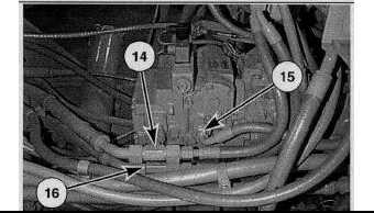
Vibratory Pump.
(14) Closed circuit loop line port. (15) Case drain oil line.
(16) Closed circuit loop line port.
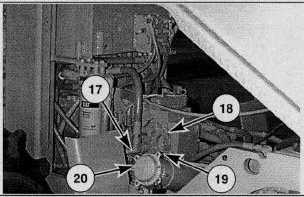
Vibratory Pump.
(17) Charge oil inlet. (18) High pressure relief valve (Low amplitude).
(19) High pressure relief valve (High amplitude). (20) Charge relief
valve (underside do pump).
The vibratory pump contains charge relief valve (10) and high
pressure relief valves (18), one for the high amplitude side of
the closed loop circuit and one for the low amplitude side of the
closed loop circuit. Both the charge relief valve (19) and high
pressure relief valves (18) are of the direct acting type.
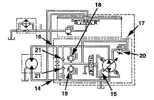
Vibratory Pump Schematic.
(14) Closed circuit loop line poet. (15) Case drain oil line.
(16) Closed circuit loop line port. (17) Charge oil inlet. (18) High
pressure relief valve (Low amplitude). (19) High pressure relief valve
(High amplitude)(20) Charge relief valve. (21) Check valves.
Charge oil enters the vibratory pump through charge oil inlet
(17). The charge pressure entering the vibratory pump is
controlled by the charge relief valve in the vibratory flushing
valve. The charge relief valve (20) located inside the vibratory
pump is used to prevent damage to the pump. If the charge
pressure entering the pump reaches 2800 kPa (410 psi),
charge relief valve (20) opens to allow more oil to flow through
case drain oil line (15) to the hydraulic tank.
The maximum working pressure for each closed circuit loop
line is limited to 25 000 kPa (3625 psi) above charge pressure
by high pressure relief valves (18) and (19). Check valves (21)
are built into the high pressure relief valves. The primary
purpose of the check valves is to keep closed circuit loop lines
(14) and (16) full of oil, to make up for internal leakage and
protect the charge system from high pressure oil when the
vibratory system is in operation.
13-13


