TM 5-3895-382-24
NOTE:
Inspect the main bearing caps and the connecting
rod caps for the proper identification mark. The
identification marks should give the location and
the direction of the bearings in the engine.
3.
Remove ten main bearing cap bolts (3).
4.
Remove five main bearing caps (4).
5.
Remove the lower main bearings and the lower thrust
washers. Keep the lower main bearings with the
respective main bearing cap.
Illustration 213
NOTE:
The connecting rod caps can be held on the
connecting rod with two bolts and two nuts. The
connecting rod caps can also be held on the
connecting rod with two bolts that are threaded
into the connecting rod.
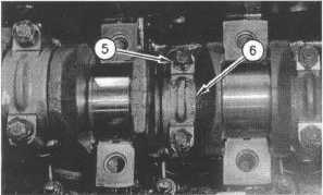
6.
Remove eight nuts (5).
7.
Remove four connecting rod caps (6).
8.
Remove the bearings from connecting rod caps (6).
Keep the connecting rod bearings with the respective
connecting rod cap.
NOTICE
Do not allow the connecting rods to strike the piston
cooling jets. Damage or misalignment may occur.
9.
Push the piston assemblies into the cylinder bores.
Illustration 214
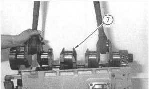
10.
Attach lifting straps and a suitable lifting device to
crankshaft (7).
11.
Lift crankshaft (7) out of the cylinder block. The weight
of the crankshaft is 29 kg (65 Ib). Do not scratch any of
the finished surfaces on the crankshaft.
Illustration 215
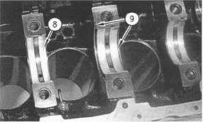
12.
Remove upper main bearings (8) and upper thrust
washers (9).
Crankshaft - Install
SMCS Code: 1202-012
Installation Procedure
NOTICE
Keep all parts clean from contaminants.
Contaminants may cause rapid wear and shortened
component life.
1.
Ensure that all of the lubrication passages are clean and
free of debris.
7-84